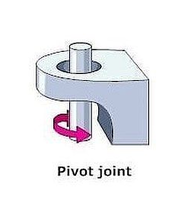
Say I want to make a flexible joint between two pieces of metal. The standard way to do that is something like this:
One side of the joint has a hole, the other side of the joint has a pin/rod.
But if I want to manufacture a joint like this, how, specifically, should I do that with a Nomad?
It’s going to be small but I want it to be as strong as it can be.
The ways I’ve thought of are:
Manufacture the hole side in two pieces that will be sandwiched together, manufacture the pin side as one piece which will be sandwiched between the two holes
This is relatively straightforward, no crazy tolerances to keep or anything
The “hole” piece can’t be made as one piece and has to be held together by some kind of fastener or adhesive, so may lose strength
Manufacture holes in both pieces, one to receive a pin with an interference fit, the other with a transition/clearance fit
Requires manufacturing the holes with tolerances for an interference fit
Requires the ability to press fit the pin without breaking the workpiece
Requires a pin held to a tolerance good enough for an interference fit
Use ball bearings on one side
Requires manufacturing holes with tolerances for ball bearings
Something else
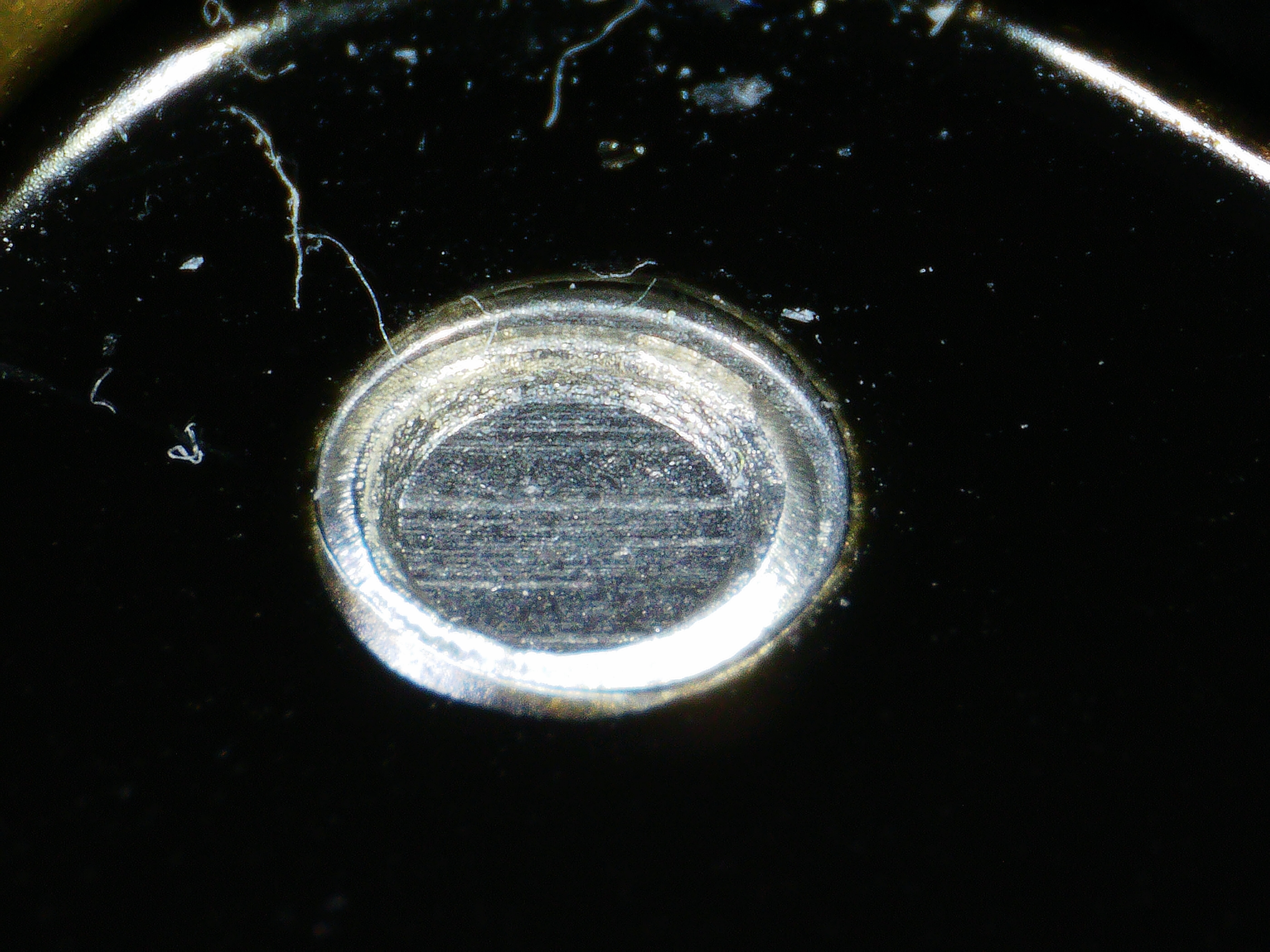
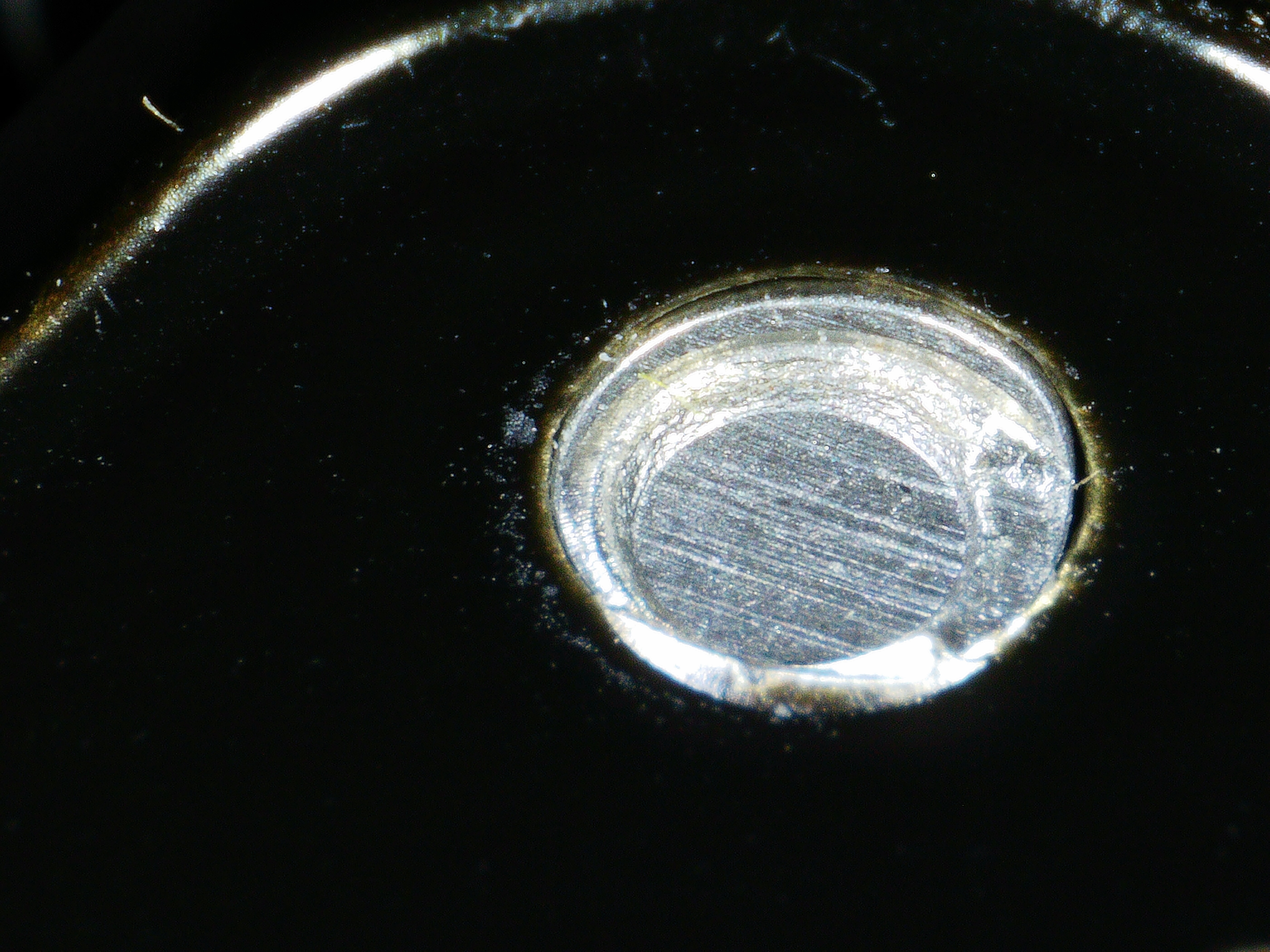
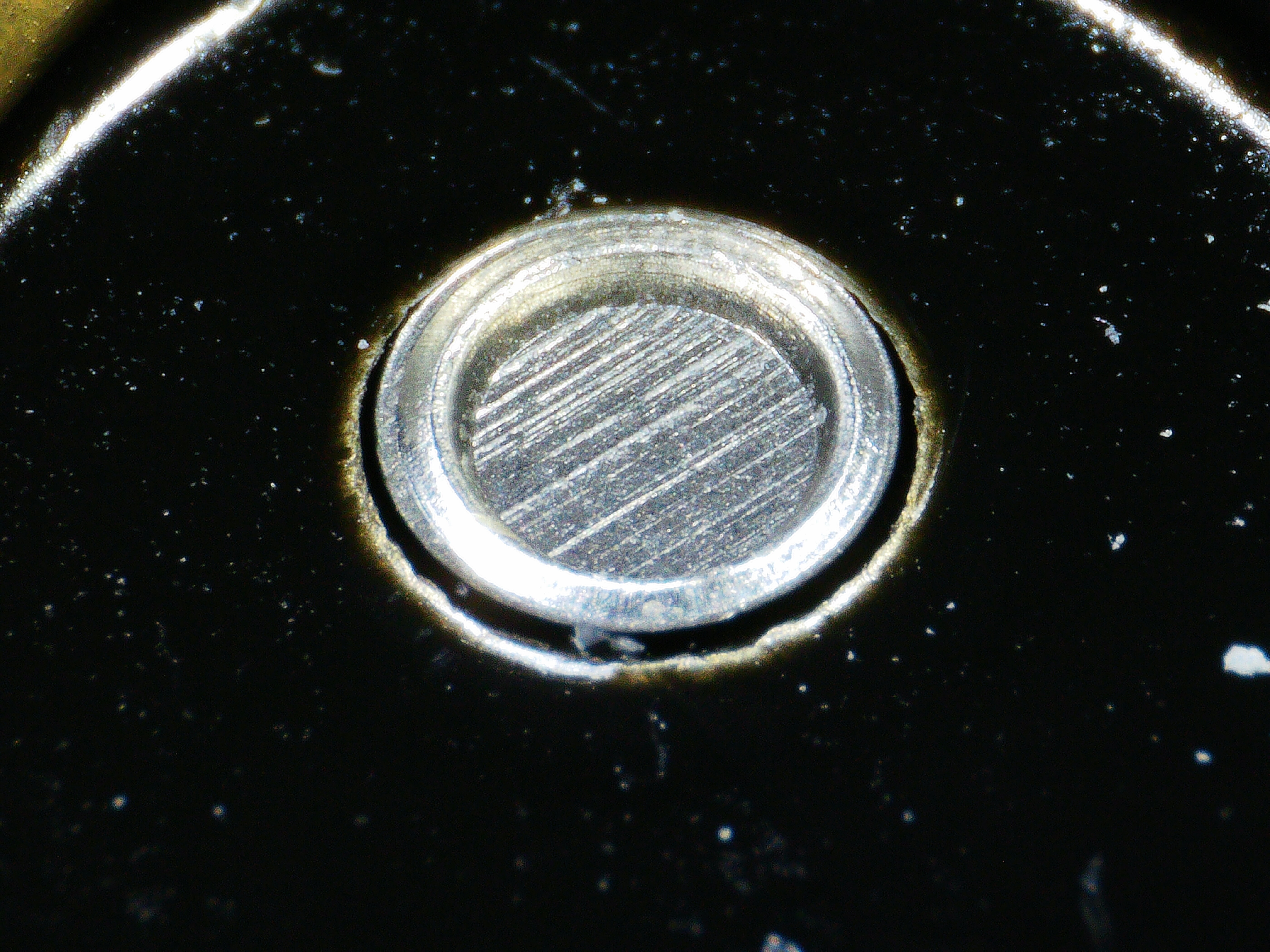
On the “something else” front, I have a buckle which has a little pivot installed through some method I couldn’t identify. Both sides, top and bottom, look like this:
I’ve no experience with the Nomad or cutting metals, but if you want a strong hinge, wouldn’t you be better to cut the hinge pieces but source steel pins separately? Either rods you could cut to length or pins of the specific length you need.
EDIT: You could even use bronze bushes between the pins and the cut pieces.
That’s what my second bullet point was, the trouble there is that the pin needs to be held in place securely. I think the way to do that would be an interference fit, which would require tight tolerances on the hole and a mechanism for pressing it in.
For example I can get 4mm h8 (-18/+0 µm) or m6 (+4/+12 µm) pins easily enough but for an interference fit on an m6 pin, I need to be able to hold a tolerance of something like ±12µm (5 tenths for the imperial folks) on the hole diameter.
Since I’m not applying torque, maybe simple glue or something would be enough though?
If you were to use a bronze bush, you could cut a vertical slot into the bush to induce the interference fit on the pin.
I did a similar thing with some aluminium tube when I was using the Sweepy v1 that came with my XXL, but that was on a much larger scale and quite easy to do.
I’m not sure if you’re UK-based or an insomniac and US-based, but Amazon sells sintered bronze bushes of various sizes here, and sourcingmap supply pretty good products.
Ah, my three favourite things - and very presumptuous of me, sorry
Having just said that, and reading your post more slowly, will the hinged part be removable, either by lifting the bottom hinge and pulling towards you, or by removing the pin(s)? That would help decide which part should have an interference fit.
I think the second option is the best, but if the pins are steel and the parts you’ll be making are aluminium, it might benefit from a bushing between them to stop any corrosion.
It looks to me like the pin has been peened over (or pressed by a machine) to stop it coming out, and the pin itself may be ridged into the fixed part. You’d need to drill this out if you wanted to remove the pin.
Maybe the best way to find out how that buckle works is to destroy it and peek at its un-chocolatey innards?
But destruction aside, my guess is that it’s like a rivet. The top of the pin was hit with a shaped punch which created the flanges that keep it in place.
(edit: ermmm… what Peter said … I should read to the bottom of the thread)
I think I might be overcomplicating things. Since there’s no torque being applied, the pin just needs to be held so that it doesn’t fall out due to gravity or something like that. In that case I can make do with superglue or Loctite 648.
The weird thing here is that the pin looks very very similar on both sides and the center looks to be completely solid, it has linear marks running along the top that look like the result of some kind of cutting process, rather than some kind of press.
My first guess was actually brazing or some kind of filler material. It could also be some kind of donut-shaped insert pressed in between the pin and the hole.
I already have a fairly good idea of how the buckle itself works (it’s a single piece of solid Aluminium), the only mystery is the pin at the moment. It’s somehow inserted through the buckle then kept in place.
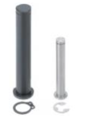
I’d really prefer for it to be flush if possible but a circlip would be fine. Do you know how to find pins with a circlip groove though? Is there a DIN standard or something I can look up?
Ah, you mean basically hold the pin in with a set screw? Not a bad idea more generally but in this case, I don’t have enough vertical space for a screw.
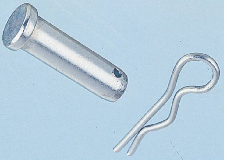
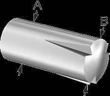
How about something like this? One end is grooved for a press fit and the other is smooth for the pivot.
The hole for the press fit is normal drill tolerance and you can press or tap the pin in place.
It’s called a “Half-groove Dowel Pin” on the McMaster-Carr site.