I was cutting a contour with a downcut bit and in order to make chip evacuation easier, I designed the cut as a deep pocket with a width larger than the tool diameter (here’s the relevant part of the design file: depth_first_pocket.c2d (825.5 KB) ).
Didn’t realize it in the path simulation of CC, but when cutting the piece I was suprised that the cut would go depth first (i.e. cutting one contour of the pocket up to the bottom and then cutting the next contour from top to bottom).
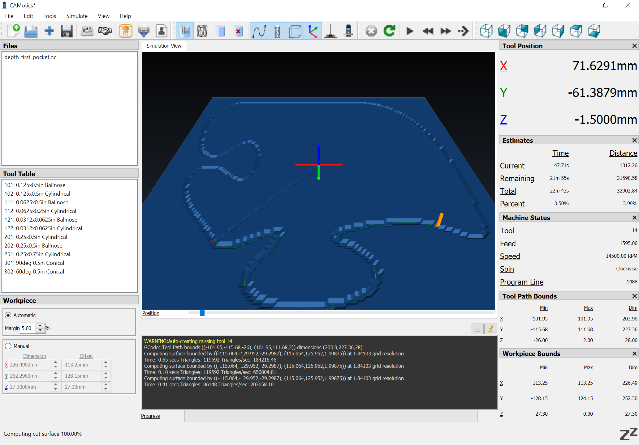
You can see that the two contour paths in the pocket are only connected via a single rapid movement:
Up until now, the pockets in my designs were always cutting fully in the XY-plane and then proceeding along Z.
How come that in the above file, the cut is going depth-first?
Hey Nils,
When I open the file the “outside pocket” toolpath says “Empty Toolpath”. Your “cut” toolpath starts at 23mm. I’m not sure if something changed from when you simulated the cut to saving the gcode, but if you were to run as I’m seeing the file, it would take a meaty plunge to 23mm first.
After I select the geometries you’re talking about I can see what you’re seeing in the simulation. It seems like it’s something in the algorithm of CM perhaps. Where you’re looking for sort of an adaptive clearing. I will defer to the experts, but you could create more toolpaths to accomplish what you want. It would be a little tedious but you would have a pair of tool paths for inside and outside contours for x depth of cut (Depth Per Pass) then the next set for x depth of cut with the Start Depth as the previous tool paths Max depth - repeat until you reach your desired depth.
This seems like an opportunity for improvement with CM.
Sorry guys, I just found my error. I must have mistakenly selected an inside toolpath in the original file.
Thanks @WillAdams, exporting again and looking at the result in CAMotics made me look twice and see what I did.

 in the original file.