I’m trying to make what should be a pretty simple set of toolpaths to cut some circles out of hardwood. No matter what I do, I can’t seem to get Fusion to stop generating toolpaths where the bit collides with the workpiece. https://a360.co/30xHTEJ
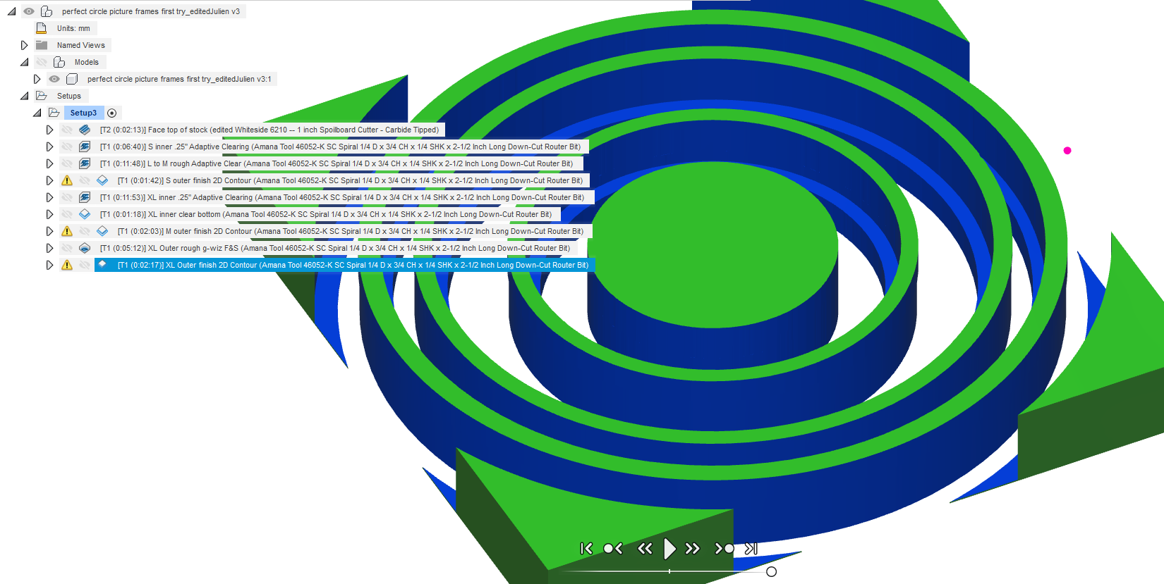
Sometimes these collisions have no effect on the workpiece, and other times it’s leaving a little channel. For example, if you look in the Fusion file I linked, the job called “XL Outer finish 2D Contour” has 18 collisions. The first 17 of these don’t do anything to the piece. The 18th moved the tool too close to the finished wall of the piece, and then retracted it, thus ruining the cut.
The final toolpath on that file, called “L to M finish Contour SO MANY COLLISIONS!” has several thousand collisions. I have no idea why Fusion is creating the toolpath in this way.
Does anyone have any suggestions for how to prevent this? I’ve searched all over the place but am having little luck.
You’re endmill has a height of 3/4", but you are cutting 30mm deep. That’s a lot of shank (non-fluted part) contacting stock. Might not be an issue. The last one may be solved with a Lead Out.
@neilferreri nailed it as usual. Here’s what I can contribute in addition. I played with the file a bit, and I would suggest various changes for you to consider:
ideally, get an endmill with 30mm LOC. This will remove the “collisions” that F360 reports. But, it’s not always easy to find an endmill with a long LOC like that, so you can choose to go ahead and use your endmill with its 3/4" LOC, and use a stepdown value that is lower than the LOC. Say 15mm: during the first pass, everything will be allright. During the second pass, the shank will slightly rub against the wall cut during the 1st pass, but…sometimes it’s not a big deal and you can get away with it. Worth trying.
I rearranged the toolpaths in the opposite order: cutting the small circle first, then the medium, then the large. This is to go from the inside to the outside of the stock, such that there is always a maximal amount of material left to hold the piece being cut. Same principle as doing profile cuts last.
note: I added the adaptive clearing on the small circle, it may not work well with your workholding method of screwing the piece in the center. I did the toolpaths assuming my workholding method (tape & glue), so you may need to tune that.
I added -0.1mm axial stock to leave, to overcut slightly and make sure you don’t have an onion skin left at the bottom. You may even want to increase that value to overcut deeper, depending on how flat the bottom of your stock is, and how well your Z is calibrated. As a bonus, it took care of a minor simulation bug (that did not show the bottom being cleared even when using “stock bottom” as the finak depth)
Since you went for adaptive clearing at large DOC, I figured you might as well push DOC up to 15mm instead of 12.7mm, this will reduce the number of passes from 3 to 2.
No need for a 1/8" endmill to cut that slot between the large and the medium circle: it is 6.5mm wide, so a 6.35mm (1/4") will do, I used a regular contour profile cut (limiting DOC to 2mm per pass) to go inside this slot. That conveniently leaves 0.15mm of stock on the other wall, which I then remove using a dedicated contour cut along that other wall.
As Neil said, no need for rest machining in this project, and I also cleaned up the toolpaths selection a bit (some had more contours than required)
Here’s my edited version of your file with the modifications listed above: https://a360.co/2PWP4UI
optimal load of 2.54mm may be a bit high (to my taste) even in wood: you can try it, and dial it down if you feel the machine struggling.
downcut endmills are great to avoid tearout on top surfaces, BUT they also have poor chip evacuation. I personnally wouldn’t use a downcut for adaptive clearing at such depths (30mm). I would instead use an upcut for the adaptive clearing, and then switch to a downcut for the finishing contour passes only
I did not bother about finishing passes on the INNER walls, if this matters you should add them.
I took a look at the feeds and speeds, and they looked OK so I did not change anything (3flute, 18000RPM, 100ipm => 0.018" chipload, should be ok in hardwood)
hopefully you have a Suckit or other fixed-height dust shoe, to mill at 30mm depth
ALL of this being said, this is just me playing with your file, there might be some mistakes left in there, absolutely do verify everything if you want to use it !
For XL Outer Finish Contour:
Unfortunately, while the first seven collisions in that toolpath were non-issues, the collision at the end actually did occur when I ran the job, and left a big divot along the side of the workpiece. Also, when cutting, do you need to have an LOC that’s as tall as the workpiece? Is it bad if the shaft of the cutter just goes along the previously cut area?
For the other one, I’ll turn off rest machining. But I don’t understand why that would make a difference. I thought rest machining just told Fusion what was already gone?
Like I said, I have it a quick look last night. To be honest, I wasn’t sure what you were trying to do with the toolpaths. I got confused by the names and the reason why you hid some bodies.
You didn’t have a lead out in that first toolpath, so when it did it’s final retract, it just pulls up along the edge of your piece. I didn’t investigate why the rest machining was giving that bizarre toolpath. I never use rest machining in that situation, so I turned it off and it worked.
I can look at it more later, but @Julien looks like he’s got it covered!
I had not even noticed you were missing the lead-out on the finish toolpaths before Neil mentioned it, I just added them in case you have not downloaded the file yet. Else you should check that lead-out checkbox yourself in the three finishing/contour toolpaths.
Oohhhhh, so that’s what lead out does? I know it’s very stupid, given the name “lead out” but honestly I didn’t realize it meant it would pull the tool away from the piece - I thought it was just another HEM term I didn’t understand. Some parts of this learning curve are steeper than others.
Ok, so first, once again, thank you very much! This level of help is truly incredible.
I ran the file - actually I broke it up into individual jobs so I could see what was working and what wasn’t. For the most part they all worked perfectly!
There are only two issues I’m finding. The first is that the dimensions of the finished parts are not correct. On the largest circle, the little lip halfway down is supposed to 5mm wide, but it’s only 3mm. Not sure why this happened. The other circles are all fine, so I’m going to run it all again and see what happens. Will report back.
The other issue I ran into was a very mysterious Z-height problem. On the “XL inner .25” Adaptive Clearing" pass, I thought I heard it lose a step or two, but then I couldn’t see any issues, so I let it go on with its work. After the job was over I checked the z-height, and it seemed to be off by 3.325mm. I reset the Z-zero to the top of the stock, and ran the next job, which cut down into the wasteboard by 3.325mm. So, it seems the z-height wasn’t wrong, after all. And generally I think it’s losing steps here and there as it cuts, though they don’t always show up.
Do you think it might be hitting the dustboot? Could that account for it? I don’t see any kind of plunge on that tool path that should cause it to lose z-steps, so I’m really not sure what else it could be. I’m fairly certain I’ve checked mechanical issues off the list. Pulley seems good, belt seems tight, v-wheels seem ok…it’s mysterious.
I have a longer up-cut endmill coming today, we’ll see if that helps.
Checking the simulation again, I can see the lip on the largest circle ending up being only 3mm wide indeed, so there’s a remaining bug somewhere in the toolpath, I’ll look at it and report.
I removed the lead-in/lead-out and the “multiple finishing passes” for the “M outer finish 2D contour” : there is barely enough space for the 6.35mm endmill to fit in that 6.5mm slot already, and the previous options added about 0.5mm extra width to the cut (plus, no real need for them for that lead-in, the nice circular ramping movement should give just as good a result)
there was 0.5mm radial stock to leave on the inner side of the XL circle, so I added a new toolpath “XL inner finish 2D contour” to shave it off.
Don’t ask my how this amounted to 2mm delta, but I checked simulation with these new toolpaths, and the lip ends up being the same width as for the other circles now.
You may want to regenerate all the “M” and “XL” related toolpaths, I’m not quite sure now if I touched anything in the XL inner .25 adaptive clearing.
Now, about the second thing: I think it may be related to the initial surfacing operation, that you setup to remove 2mm of material. In the project, the stock thickness is set to 30mm, same as the model thickness. But then your first op is the surfacing, which removes 2mm. If you stopped at some point, and re-zeroed on the top of the piece…you zeroed 2mm lower than initially, hence now cutting into the wasteboard (not sure where the 3.325mm comes from though).
So:
where did you measure that the z-height was “off by 3.325mm” ?
is your stock actually 30mm thick in the beginning ?
do you want your final piece to be 30mm thick (in which case you need a thicker stock to begin with, OR don’t do the surfacing), or 28mm high (in which case, it should be modeled that way, and then the toolpaths can reference the “model top” rather than “stock top”)
The settings for the XL .25 adaptive clearing are not very aggressive Z-wise, it would be surprising to lose Z-steps there, but you can still reduce DOC further: downcut endmills don’t like deep slots so much. The problem (if it was not linked with the surfacing op story) might go away when switching to an upcut.
One thing, just in case anybody ever is searching for this, the Shapeoko does not seem to re-home itself after a cut, the way the Nomad does. I had to quit CM and then reconnect the cutter to get it to initialize itself.
In terms of where I measured the Z-height: I measured it after I ran the job, meaning I sent the cutter to the xy and z+6 offsets, then moved it down by 6mm, only to discover that it wasn’t touching. I then lowered it and re-zeroed using the old rolling-paper method, and the amount that I noted before hitting ‘zero’ was -3.325, meaning I had moved it down by that amount. Then that next job cut about 3.325mm into the wasteboard, so I re-zeroed the damn thing using the same procedure, and it was exactly the same amount off, but in reverse. I’m totally sure now that I heard it lose a few steps, and the only thing that makes any sense to me is that it hit the suckit dustboot.
I don’t think the lost height is due to the surfacing. I just use that toolpath separately to surface one side of the stock before flipping and surfacing the other side, after which I suppressed it and measured the existing stock at 30mm.
I’ve got a much longer up-cut bit coming today, hopefully, so I’ll see if that helps with the z height.
Just so you know, if you really need to, you can re-home using “$H” in the MDI menu. But usually, it’s better to do all toolpaths without re-homing.
Not sure what’s going on with that 3.325mm offset, it’s hard to picture the actions you did in details from here. You can reduce depth per pass from 6mm to 3mm, and lower plunge rate to say 400mm/min, in that adaptive toolpath to minimize chances of losing Z-steps.
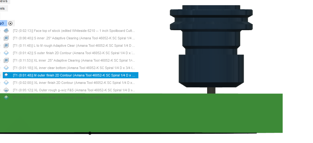
Definitely check beforehand if the collet will collide with the suckit shoe when cutting the last passes, if the tool is modeled correctly, the collet will be very near the surface:
You can’t, I cheated, I went to “top” view in the simulation, zoomed in, and used a ruler on my computer screen to measure how wide the “correct” 3mm lip was, and checked that I found the same width for the corrected one. Don’t tell anyone I resort to such ugly shortcuts
Glad I am not the only one with a scale next to their screen! Did that yesterday to make sure my facing operation over a section of stock was wide enough for the subsequent contour operation underneath.
The problem with the makita/carbide router and the suckit dustboot is the housing for that little locking button thing on the router bangs against the boot. I’m going to need to modify the boot a bit, I think.
Update: I bought a longer up-cut endmill, adjusted F&S for it, and it worked great! Everything cut cleanly, and the dimensions came out correct. All that remains is to get the toolpath dialed in for best possible results. Any suggestions as to the following would be very helpful:
Tear out:
I’m getting some tear out on the vertical surfaces. This is not unexpected, since I’m cutting circles, at certain points in the cut I’m running through endgrain, but I need to minimize it so I have less sanding to do. I thought maybe the thing to do was leave about .5mm of stock in the roughing pass, and then take that off in the finishing pass.
I’ve also reduced the speed from 2540 to 2100 in the finishing passes to provide a better finish. Is this enough of a reduction, do you think?
Vibrations!
I’m new to using a larger machine (at least compared to my Nomad), so I’m uncertain of how much vibration I should be feeling. When it’s going at 15mm DOC, taking its little adaptive swipes, you can feel the floor vibrate from several feet away. Is that normal? Or should I go a little easier? In case it matters, the building is an old wooden warehouse that is not in great condition.
Chatter
I’m also seeing some chatter on the wood after the roughing pass. Is that normal? It got cleared away in the finishing, but should I slow it down/go shallower?
Once again, I really can’t thank you enough for the frankly amazing amount of help you’ve given me!
In case anyone is ever searching for collisions and Fusion 360, I wanted to put this here:
any time the shaft of the tool touches the workpiece, Fusion will consider it a collision.
Even if it’s just a deep cut where the flutes are going along the bottom of a vertical surface while the shaft of the tool is rubbing along near the top (which I know is not ideal but can be done in a pinch, especially in wood or foam), Fusion will flag it. Your LOC must be as deep as your actual cut, or Fusion will light it up like a scary red X-mas tree.
I would do the finishing passes (only) with your previous downcut endmill, downcuts are wonderful to clean-up those top edges. And if you can get your hands on a downcut endmill that has a 30mm LOC, even better, do a single finishing pass at full depth, it should leave you with smooooth walls.
Nope, you should not be generating earthquakes
My gut feeling (that I mentioned above, somewhere) is that an optimal load of 2.54mm is too high, even in wood. I would dial that down to say 1mm and retry.
Ok, I’ll give that a try. I think I don’t understand optimal load. I thought it was essentially just the step-over, but I gather it might be more than that. But basically I’ll be going from 40% to 15% of cutter diameter, which I think will make the cuts take way longer. If I kept the optimal load higher - say 2mm or 1.75mm - but went shallower, would it have the same effect?