The problem is OpenSCAD does not have the facility for processing text, so can’t directly use G-Code as is, so it will be necessary to have two outputs in parallel:
G-Code
OpenSCAD code where each command matches a G-Code command
This will require a tool which exports the two different files, or a tool which converts G-Code into this OpenSCAD format.
I guess one would model the stock and then basically subtract each toolpath from it, so that you see what’s left afterwards. Assuming openscad does subtraction well enough
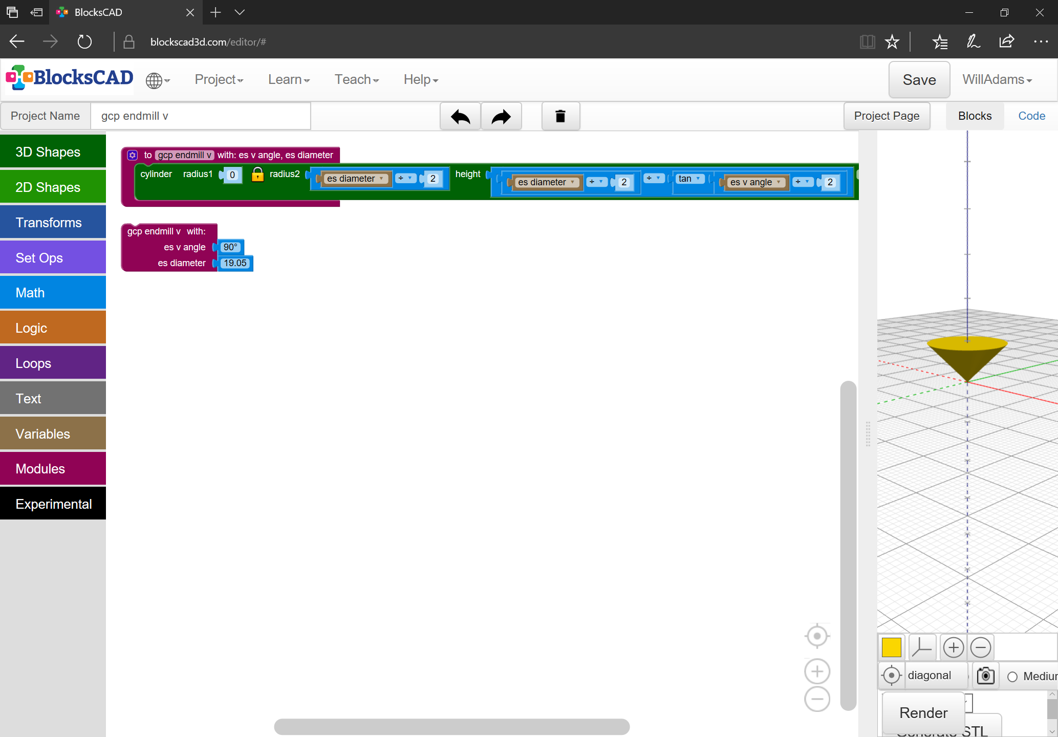
hmm maybe but wouldn’t you want it not a pure V but more the path of a V… so more or less
2 V cylinders (begin and end) and then some triangle-bar shape between them?
It’s of course possible to just do a lot of these little cones in small steps from eachother to emulate a path… it is not always a bad idea to do things that way.
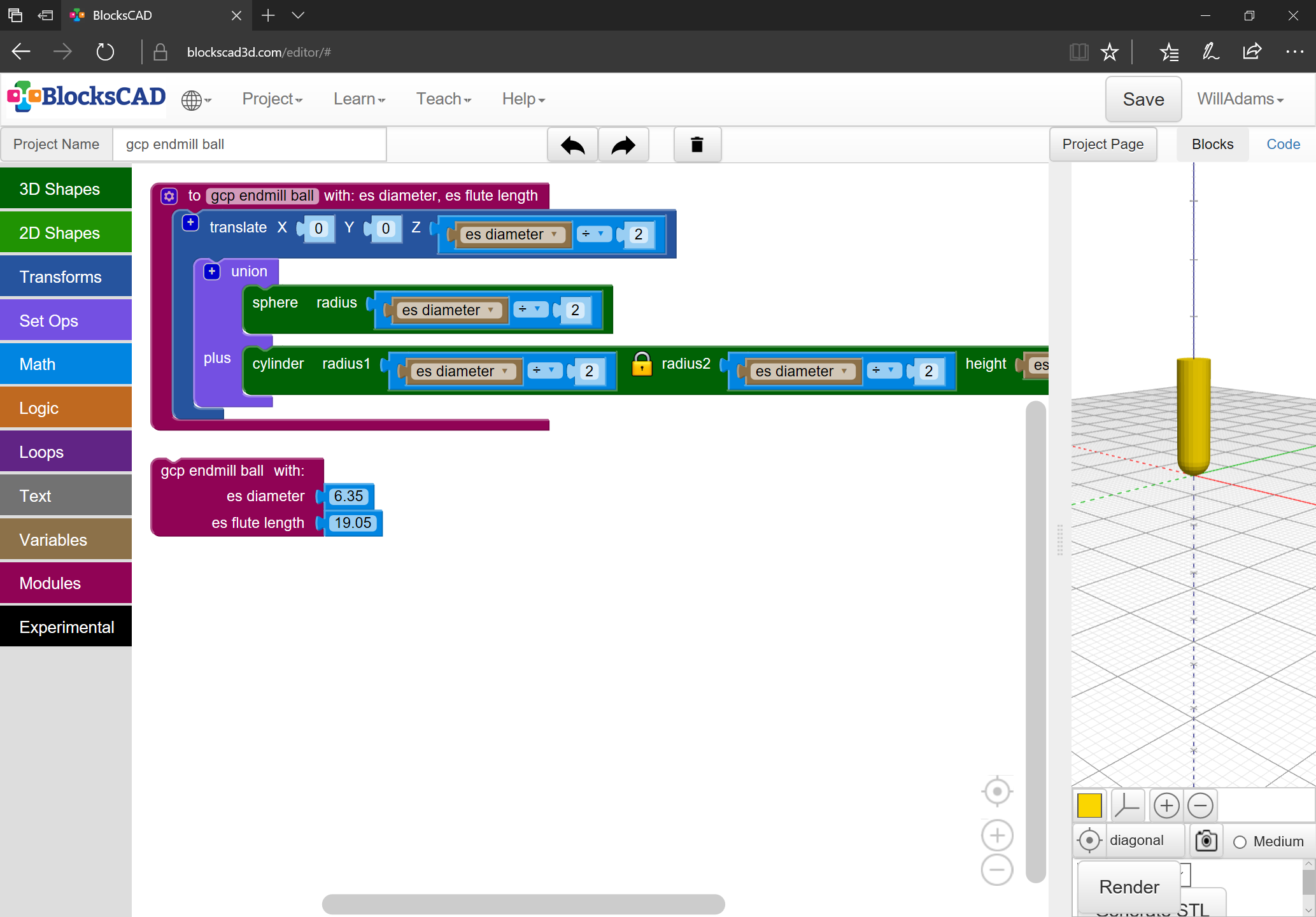
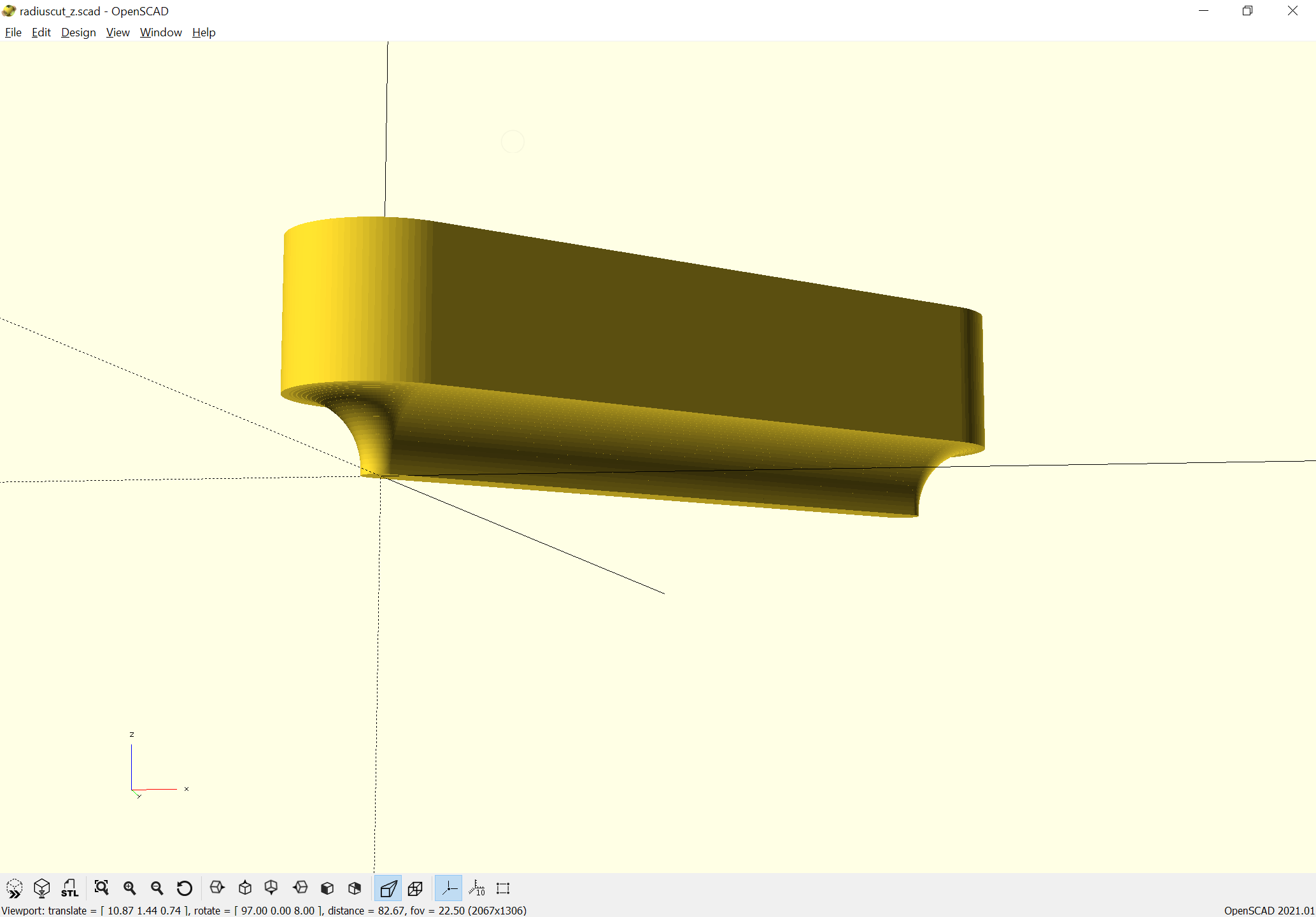
OpenSCAD has a Hull operation which allows combining two instances of an endmill for most sorts — that rather naturally brings us to the next sort of endmill, one which Camotics does not handle, cove radius endmills — it’s not workable to merely hull two instances, they have to be handled as a series of stacked angled cylinders.
So, we need to define a module which includes the coordinates for the beginning and end of the cut, as well as an input for how detailed it will be modeled as, in addition to the actual characteristics of the endmill itself.
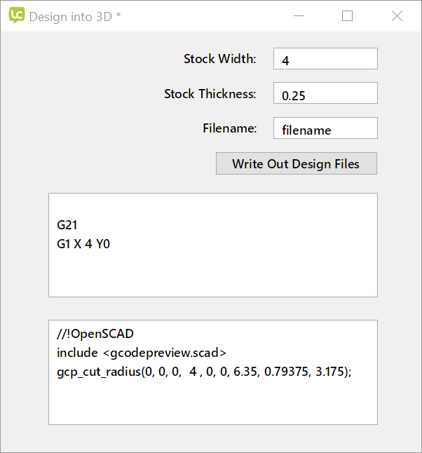
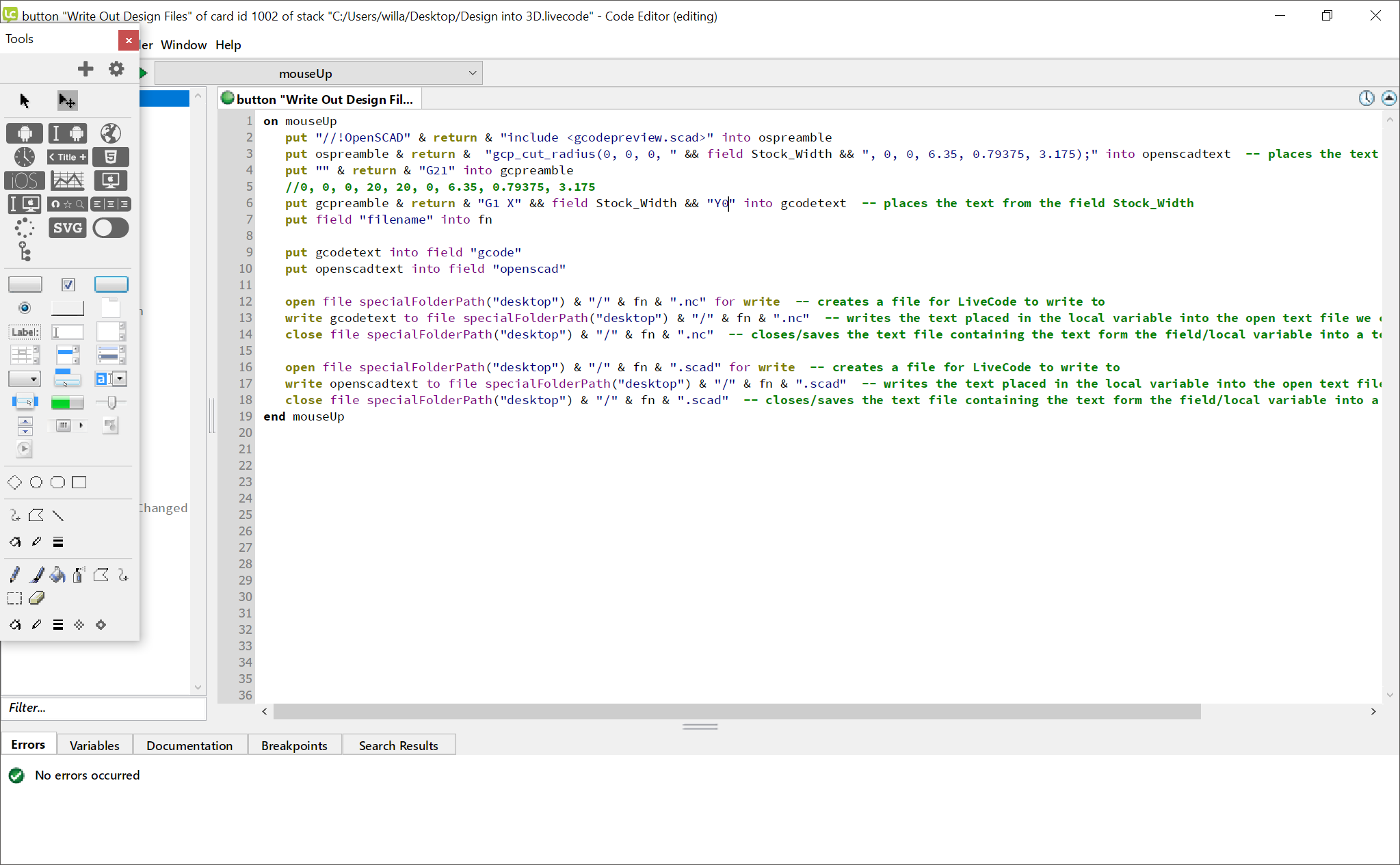
We put the commands for cutting into a .scad file and import it as a library and we can then have a LiveCode (or other) program which writes out the two sorts of files:
I’m hoping to just code the OpenSCAD end of things so that it’s orthogonal to G-Code — that’s not quite doable, since G-Code implements a given command based on current machine state, but I will hopefully manage something reasonably close.
the gcode parsing I normally do ends up converting gcode into a series of do_something(X1,Y1,Z1,X2,Y2,Z2) which seems to match the building blocks you’ve been building.
(even G2/G3 gets made into a series of small linear segments)
Some gcode (like Carbide Create) can also tell you the size of the stock and some properties of the tool (like diameter and ball radius)
Yeah, I’ll be writing out suitable comments and so forth, once I get that far along w/ things.
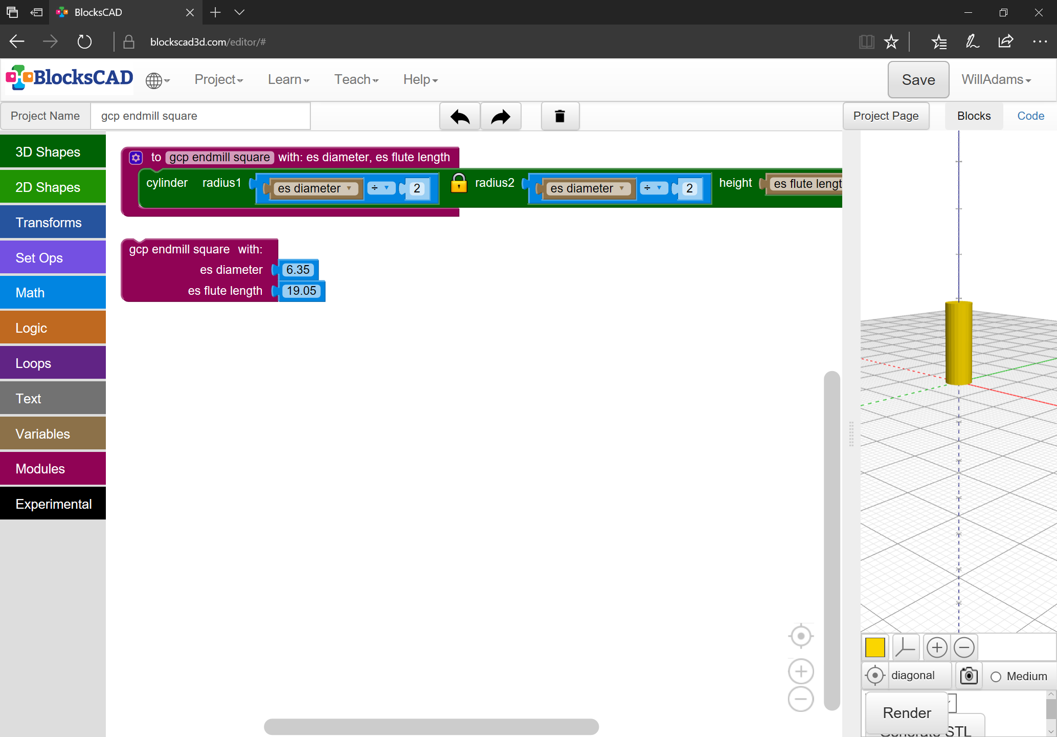
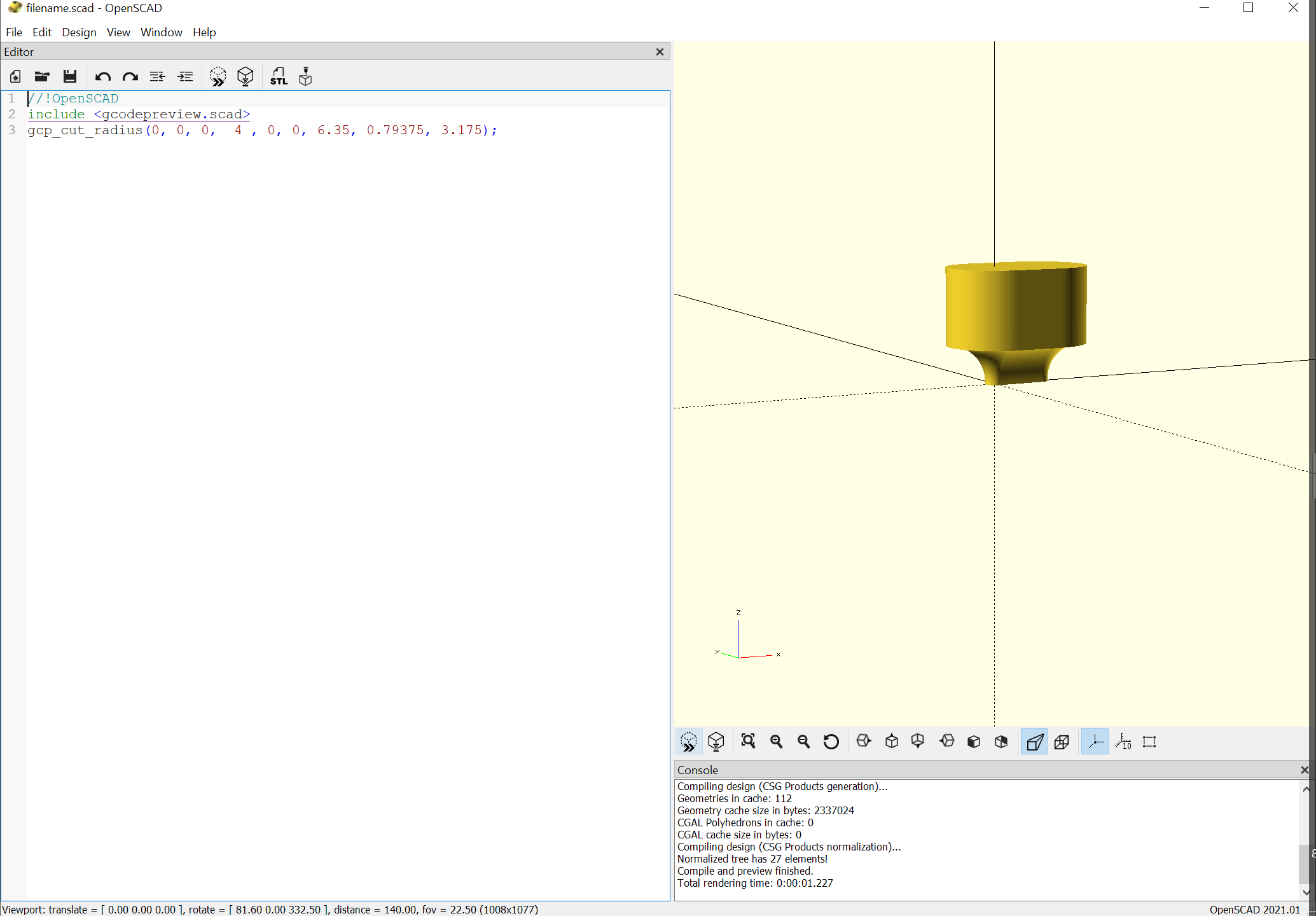
Next up is encapsulating the G-code previews so that they will cut (will have to separate out the radius cut module since it’s not in BlockSCAD), which turns out to be quite simple:
but obviously it needs a module to select the correct module and parameters based on the tool # — if OpenSCAD had a facility for processing text we could import a .csv, but in the absence of that, we brute force it.
Once I’ve got the OpenSCAD end of things finalized, I’ll put it up on Github and anyone who find it of interest/use can make use of it — I’d love to see a tool which would accept G-Code and output a .scad file for this.