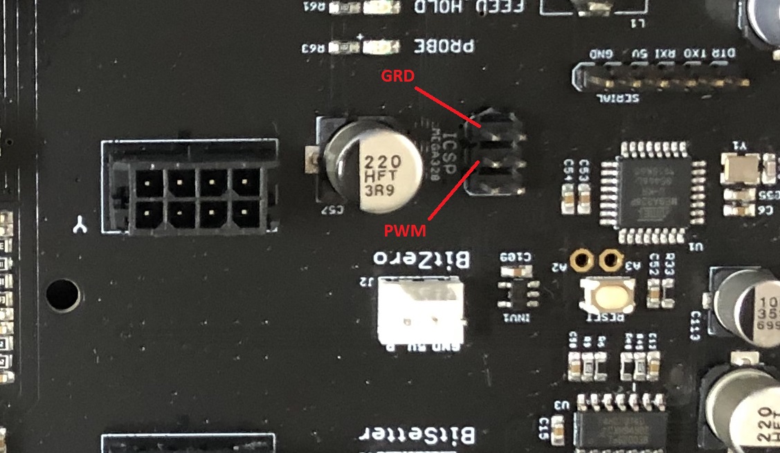
I was hoping to add a LASER to my Shapeoko Pro in the near future. I would rather not press fit or solder anything onto the control board. Does anyone happen to know which pins on the ISP portion are for PWM and GRD?
Also, I recently added a BitRunner to my machine and am now experiencing some machine disconnects. There really is no predictable pattern to it. Sometimes, I will be a few hours into a cut when it happens.
Everything is on separate circuits and grounded to separate outlets and circuits (dust collector, router, and machine). I know enough about electrical to be dangerous, so I was hoping some of you might have some suggestions.
I guess you could verify which pin is PWM by sending M3Sxxx (with xxx = half the value of your $30 setting), and checking which set of pins read ~+2.5V
Yes, there is a subtle hint in the labeling, “ICSP / MEGA328” relates to the main arduino controller where GRBL lives and that generates the PWM. The other one is “ISP1/MEGA16U2” which is the core taking care of USB comms bridge.
I’m moving my JTech from the SO3 I sold to a friend to my SO4… which uses the same board as the SOPro. Personally I just bought the JTech press-in for the PWM output on the board that isn’t populated. My reasoning is that they’re unlikely to use that for future upgrades, so it won’t get in the way.
That’s a good point Josh. I guess I am probably just delaying the inevitable for when I am ready to add a spindle. When everything is done, I will probably end up using both anyway.
In case anyone was curious though, I did some testing per Julien’s recommendation. I attached a photo showing the pins that I had about 2.67v for with a M3S500 command, and it was the same reading for the other area requiring a press-fit or solder.
I saw that. I was just curious about the tool. I have some press fit headers (“Hammer Headers” for raspberry pi), but they take quite a bit of force to insert.
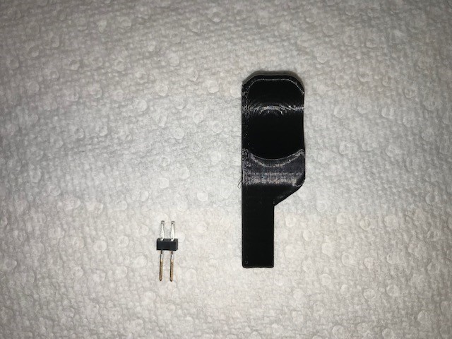
Neil it’s just a 3D printed piece that has holes for the pins to fit into it to hold the header and then it’s tapered so the user can pinch hold the tool and apply force more comfortably.
They do take more force than my brain wants to allow… but I’ve installed them on 3 controllers without trouble. I have 2 sets to install this weekend, one on my SOPro, and one on my SO4. So I’ll let us know how it goes with them.
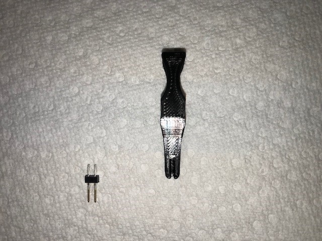
Neil, here are a couple of photos from the LASER kit. It is pretty small and held with two fingers. It almost looks like a fuse puller except that it has a smaller open end to accommodate the size of the pins.