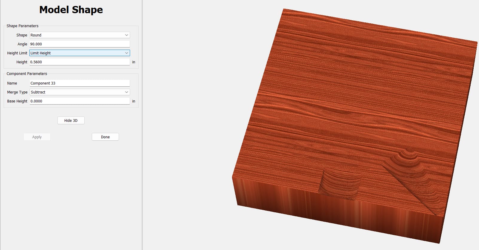
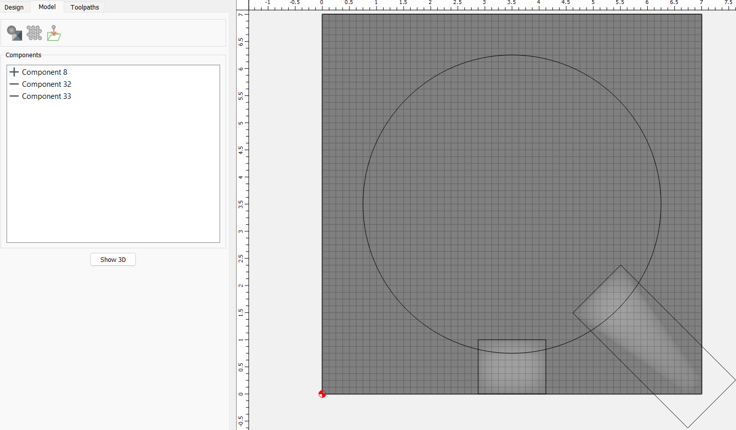
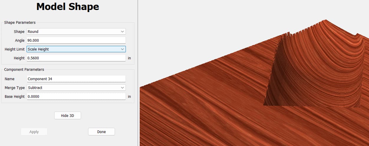
I am trying to create a cigar ash tray and having problems with modeling the channels that hold the cigars. I’m trying to make them a round channel with a consistent radius, as though a 1.25" ball mill was passed through the block at a depth of 0.56", but I’m seeing it either taper as shown in one image or curve upward (shallower cut) as it moves toward the edge when I use the boolean tool. The part that is confusing me is that when I model a rectangle to align a flat with the flat of the base square block, I see the result I’m looking for…roughly. However the same shape modeled at the corner where I want the feature either tapers or does not maintain a consistent depth. Any thoughts?

Nailed it! Thank you very much! Follow up question, when I do 3D Rough/Finish will it cut just the channel or will it contour the smaller square shape out of the stock?
3D roughing and finishing passes will cut the areas encompassed by the geometry which they are associated w/
I’m not really clear on if that was a yes or a no.
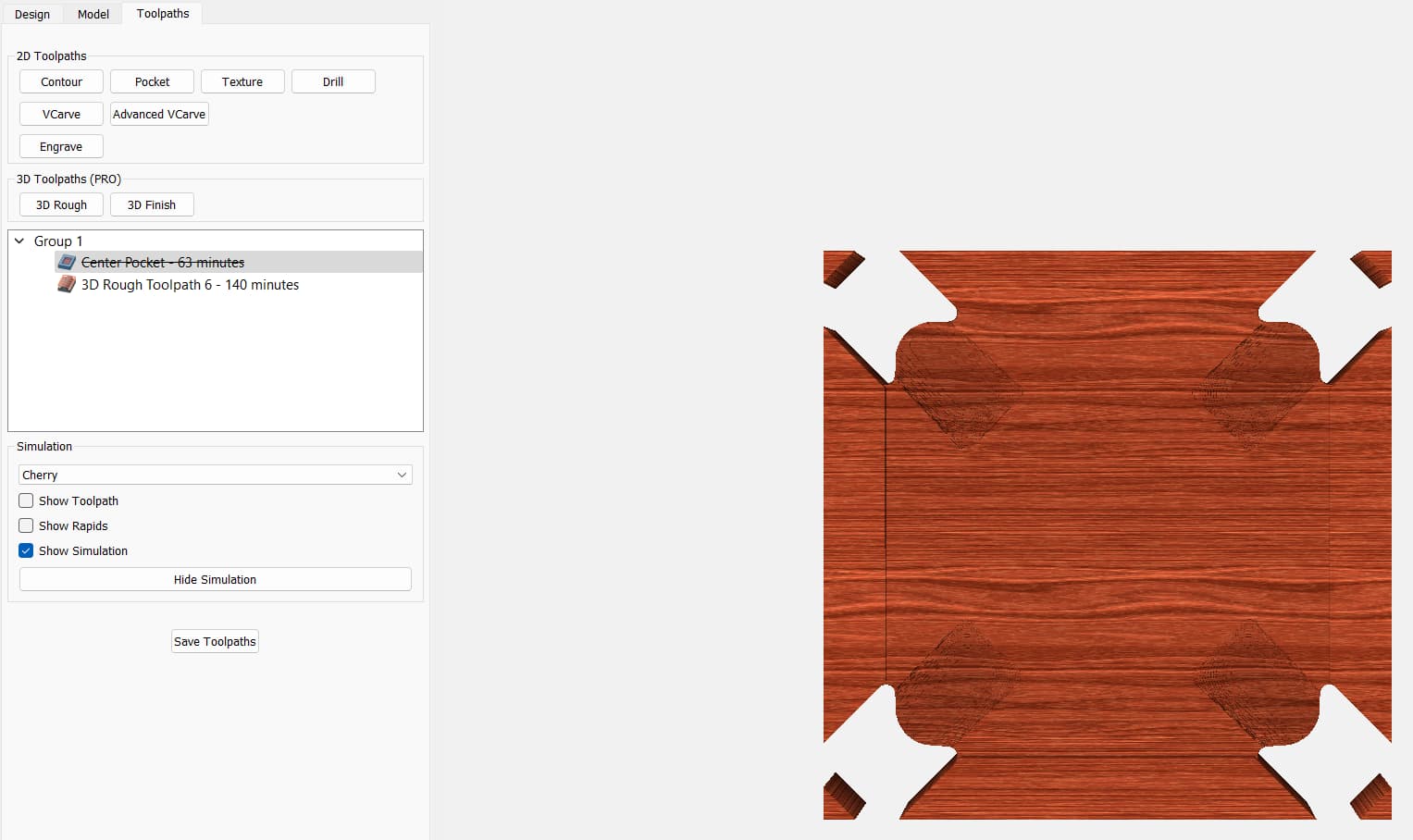
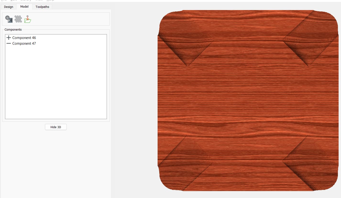
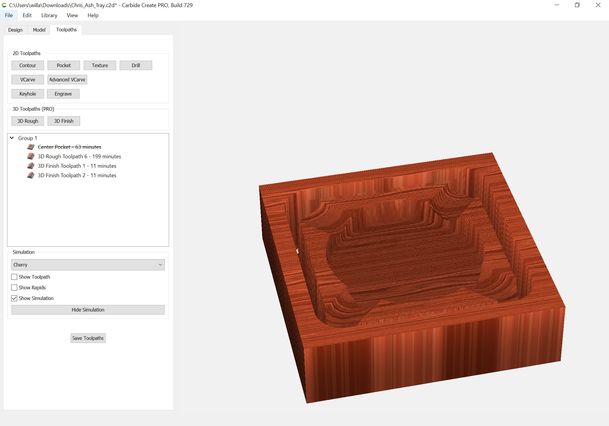
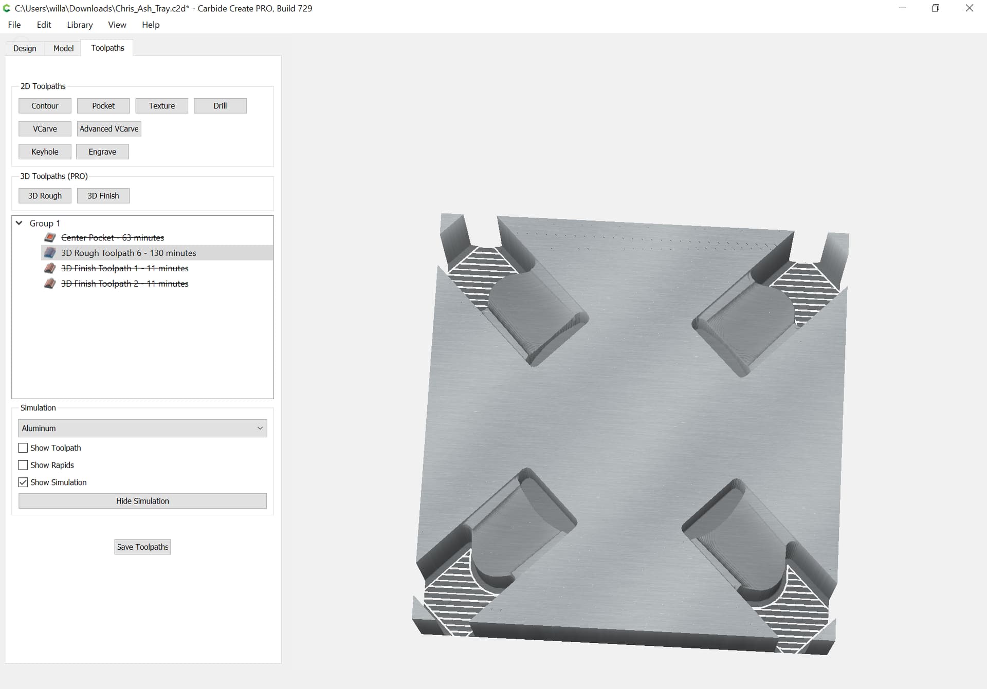
Here’s why I’m asking. The simulation views are different between the model window and the toolpath window. I’m trying to avoid the result in the top image where the tool cuts all the way through the stock at the four corners because it makes a very long unnecessary cutting path.
Post the file?
It’s almost always better to over-model, then restore material.
Chris_Ash_Tray.c2d (2.3 MB)
Why not model everything?
Then you can cut the whole thing out using a pair of 3D roughing and finishing toolpaths.
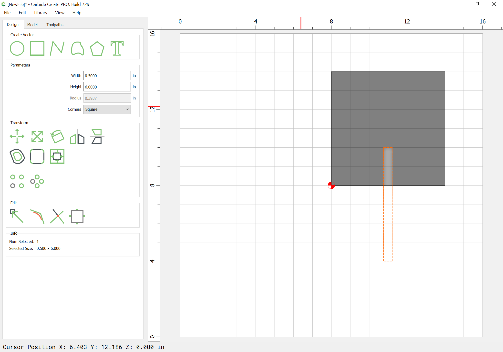
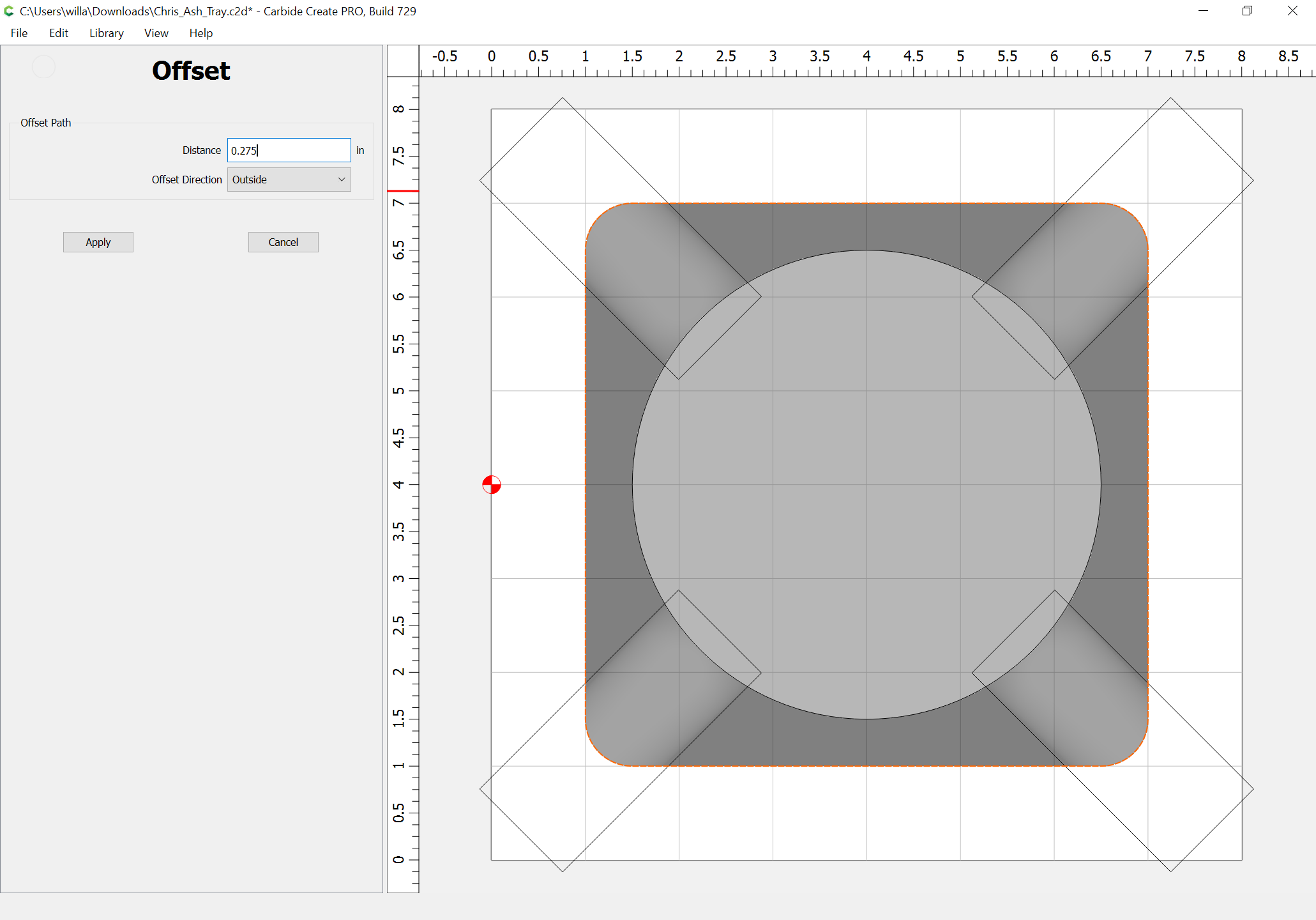
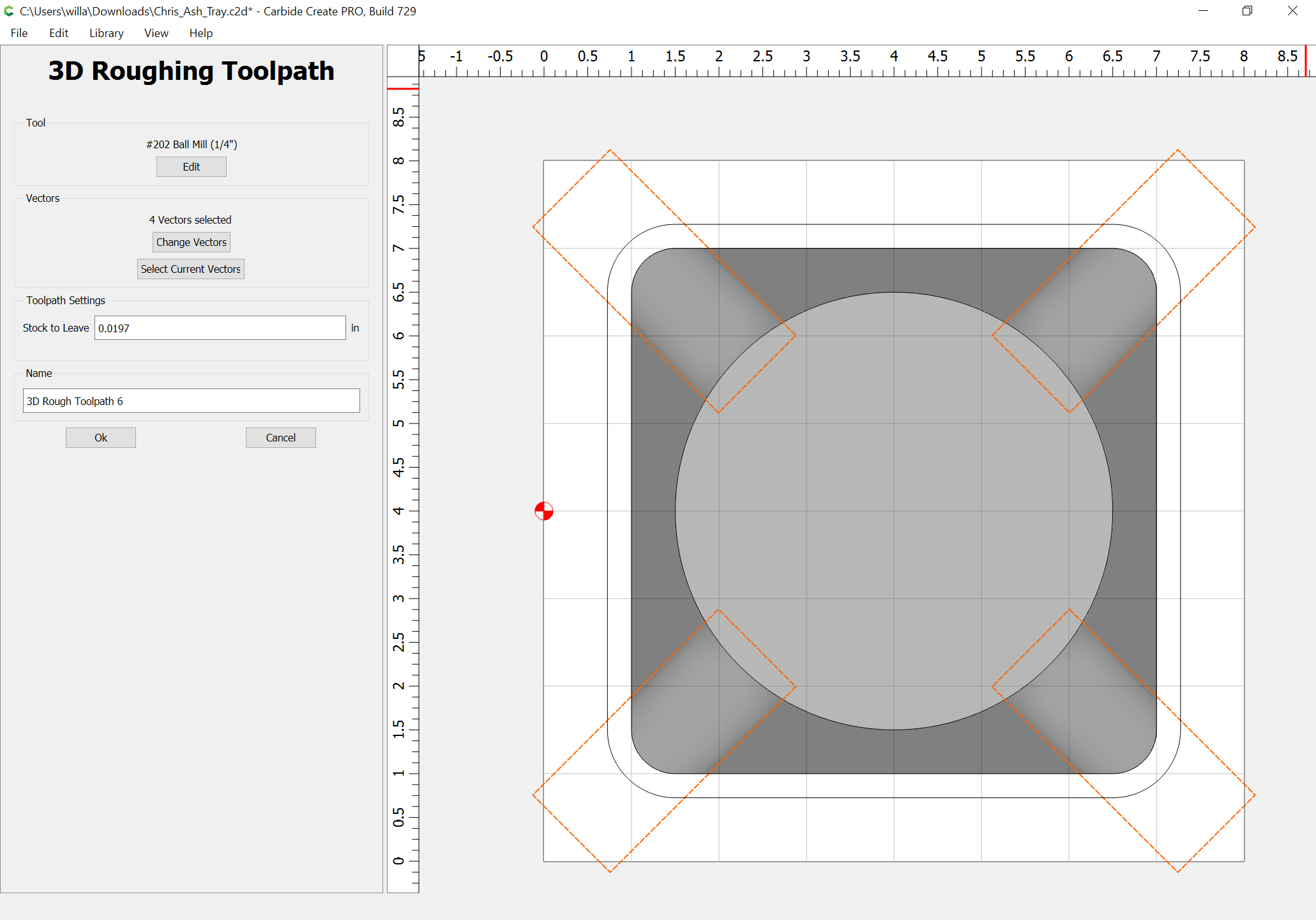
First, offset the perimeter geometry by endmill diameter plus 10%:
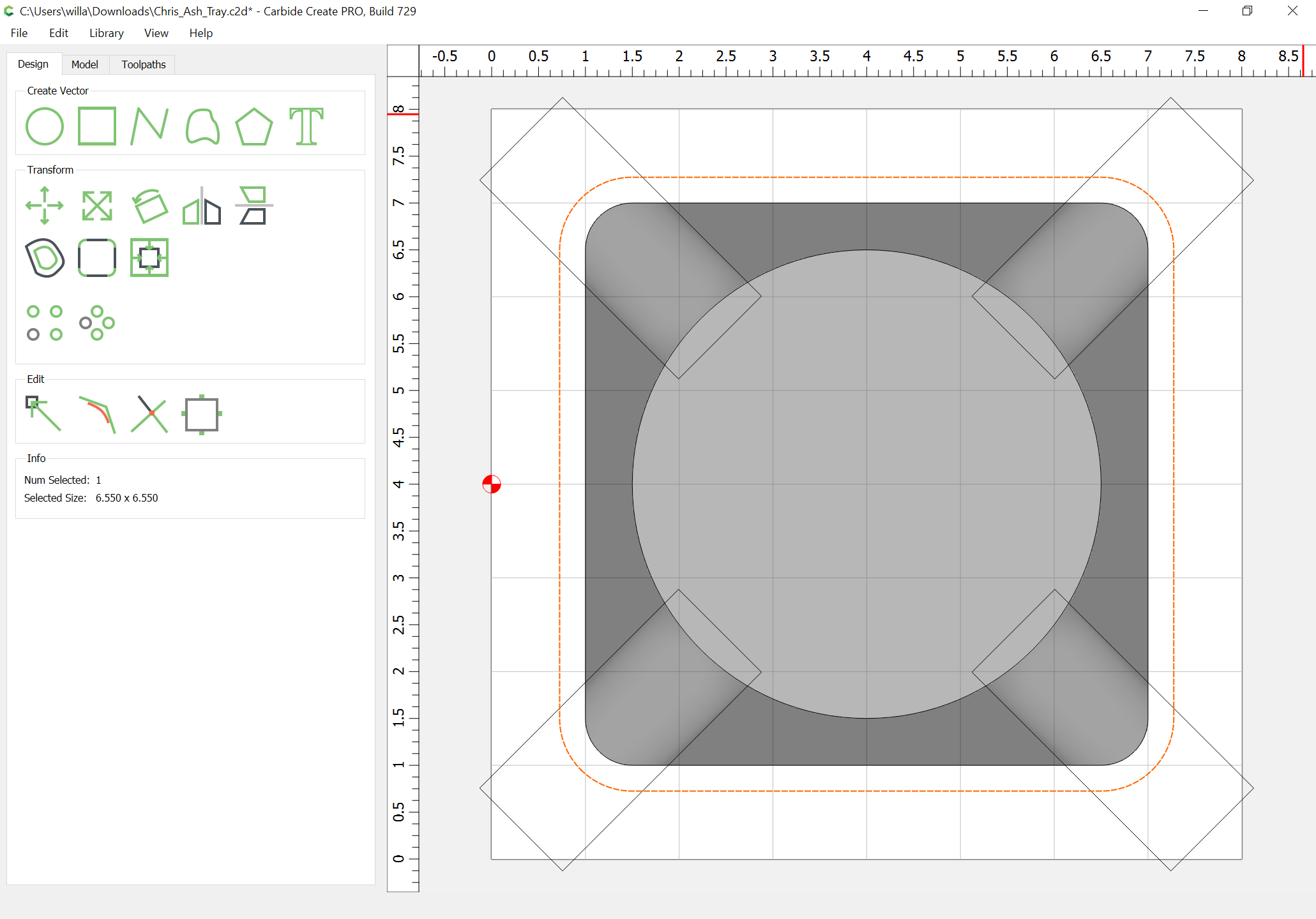
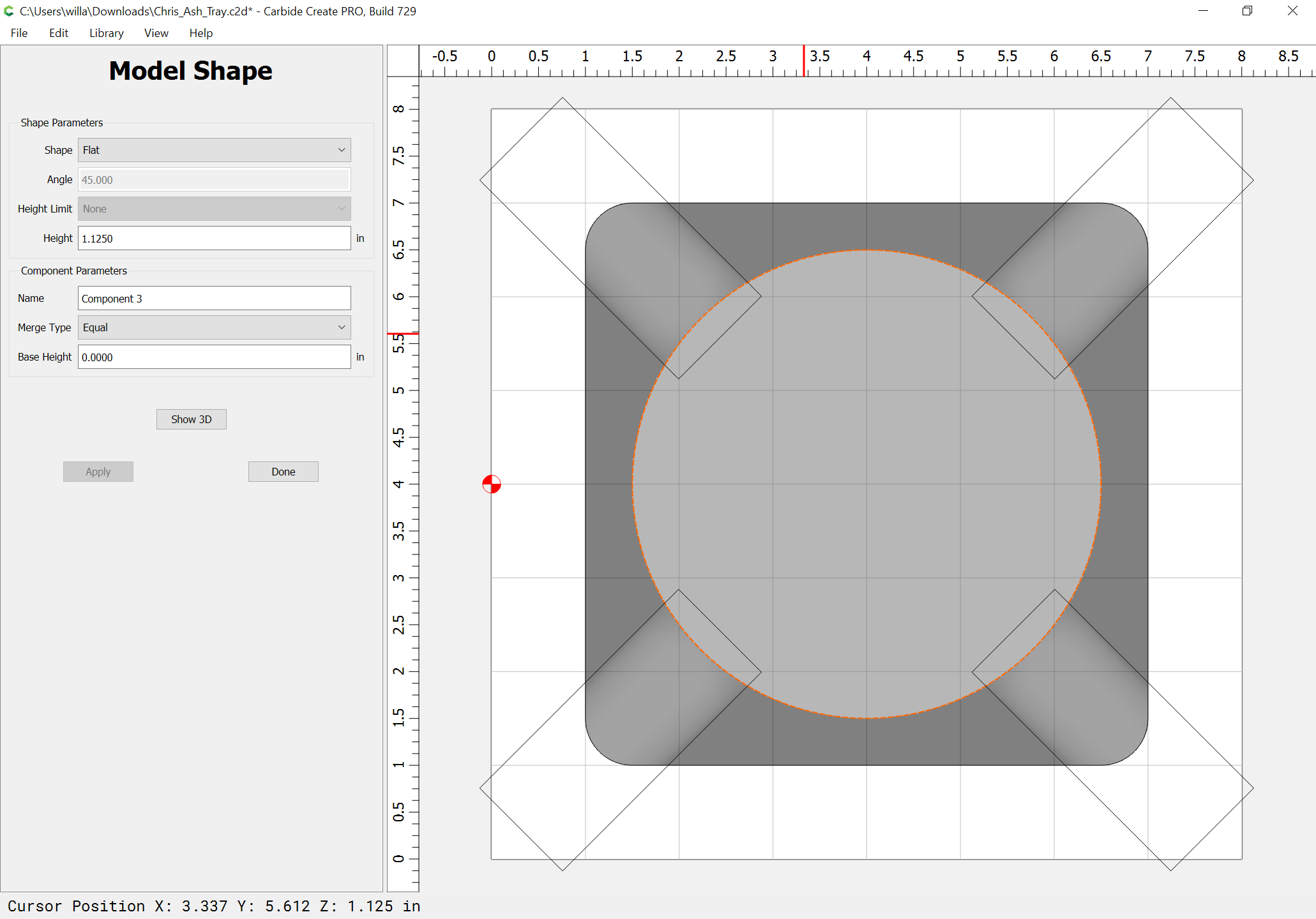
Then use that geometry to define where the 3D toolpaths are cut:


The reason you were getting the over cutting was because you had included regions twice — if you had removed the perimeter geometry, the result would have been as expected:
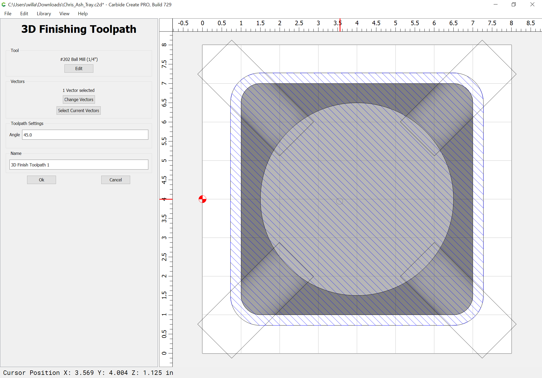
Ok this is interesting and helpful. I am not well versed in the 3D tools and am trying to learn as much as possible. What does the Angle value of 45 degrees and 135 degrees under toolpath settings do? Also, why do you do two finishing passes?
The angle values change the angle at which the tool moves.
Used two separate ones so that the angles of the cutouts could be matched.
Best way to learn the 3D stuff is to just experiment w/ it.
I did write up some basics on this at:
and if you’re unfamiliar w/ 2D CAD/vector drawing see:
and for toolpaths see:
1 Like
This topic was automatically closed after 30 days. New replies are no longer allowed.