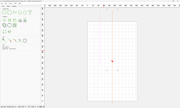
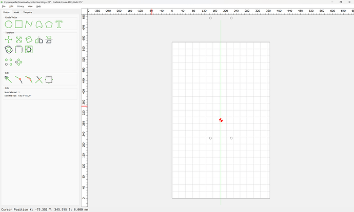
Hi everybody, I’m new to the forum and I’d like to ask you a question to solve my problem.
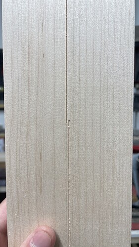
I tried to mill a straight centerline using toolpath tiling, the workpiece is secured using pins on my waste board so there’s no placing error when I move the workpiece. The problem is that the centerline I’m milling actually comes out offset by more or less 1mm when I load the second tile gcode. Any help would be much appreciated, have a nice day!
Post the file?
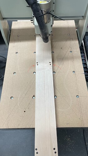
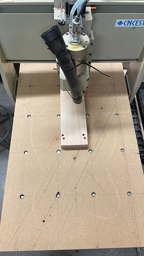
Overall photo of your setup?
How did you do the alignment and shift?
center line tiling .c2d (100 KB)
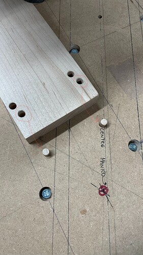
this is the actual file, ii have positioned the locating holes accordingly to the position of the alignment pins on the spoilboard.
i position the workpiece on the pins and clamp it down, then i run the gcode for the bottom tile, after that i shift the piece on the pins again and run the gcode for the top tile, but then then the centerline is milled offset by the previous one by 1mm. (please don’t mind the 8 total holes on the blank, i’m using only the ones you see marked in red).
What is the length of the board?
A deviation of 1mm over 16" is 0.14098 degrees.
Why not secure an edge guide and mill the edge of it so that it is perfectly in line with the motion of the machine?
The board is 800 mm long.
I thought the problem could have been caused by not having a square and true edge guide so I went and tried to run those two same Toolpaths on the workpiece without actually moving it and I got that same exact 1mm offset between the two tile toolpaths… that’s why I was wondering if this could be a software problem or I’m missing a step somewhere in the CAM procedure.
Post the file and the generated G-code?
I tried loading the CC project along with the pictures but apparently only the pictures are showing. How can I upload the CC file and gcode?
centerline tiling.nc (2.5 KB)
center line tiling .c2d (100 KB)
Ok, looks like they’re uploaded now.
I edited your original post so that they would show.
The Carbide Create file seems fine.
Got it, thanks. What do you think is actually causing the issue?
Could it be that the machine selected on Carbide Create (shapeoko 5 pro) differs from the CNC i actually have therefore causing uncompatibility issues? everything else other than toolpath tiling worked just fine. (i’m using the Generic gcode option as a post processor).
Machine selection is entire cosmetic — it doesn’t do anything beyond function as a reminder.
Next things to look at would be the generated G-code, and the mechanical functioning of the machine and how square it is.
the machine appears to be nicely square, as said before i’ve had good results with everything else other than the tiling operation. regarding the g-code, i’m not so practical in interpreting it, it’s actually something i don’t know how to do. by the way, i’ve uploaded the gcode too, is it possible for you by any chance to check it out for me? thank you very much for the help.
Are you turning the part around?
I noticed your centerline isn’t exactly centered between the dowel holes

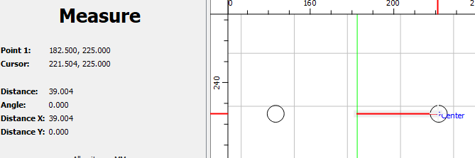
Although it’s only 0.008mm off
Your centerline isn’t perfectly vertical
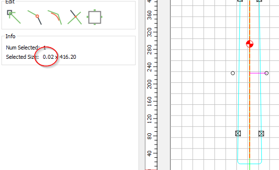
Although it’s only 0.021mm off.
But you can see it in the G-Code
G0X-0.005Y153.385   (Starts at X-0.005)
Z0.250
G1Z-0.500F300.0  (Feeds down to cut depth)
X-0.027Y-262.813F400.0   (Cuts to X-0.027)
Z12.700
I would expect X should always be 0.0 ??
Thanks for the tip! i always find a bit difficult drawing a line perfectly vertical, do you have any tips on how to make it as vertical as possible? (i’m working with this software since a week or so, i’m a bit unexperienced with it).
By the way, if it was matter of not having a perfectly vertical line i should have the problem of the line being crooked and not like on the first picture,right?
The line is perfectly vertical — you can check this by selecting it — the width is 0.000
Easiest way to draw orthogonal lines is to use the grid and put the beginning and end points on grid intersections.
I went to the Contour Path 7 (the only one enabled) and used the “Select Current Vectors” in the operation. Then back to the Design tab to see the width is 0.02
And the G-Code clearly shows different X values.
There are several lines, and several paths??
These differences do not add up to being a full mm off. So something else is going on.
And with tiling it should still line up a line that is on an angle.
Before clamping, when you align the part on the dowel holes, how much can you move the far end? (side to side)
Strange.
If you select the geometry directly in the drawing pane:
width is 0.00
If you edit the toolpath and select current vectors:
width changes to 0.02
This topic was automatically closed after 30 days. New replies are no longer allowed.
