I’m finally getting around to installing my proximity switches. I looked at the riser board and see 5 pin positions X, Y Z, P, F - I’m pretty confident I can figure out what X, Y & Z are for, but what about P & F? I didn’t see anything in the documentation about them.
P is for Probe, it’s an alternate location to plug in the…probe.
F is for Feedhold, it can be used to hardwire a feedhold button, see this thread
2 Likes
Thanks Julien. I was hoping one of them would have been for the PWM to make it easier for my laser and (soon) spindle
for PWM one easy thing is to use the connector that is one the side (newer boards) for the bitrunner 
2 Likes
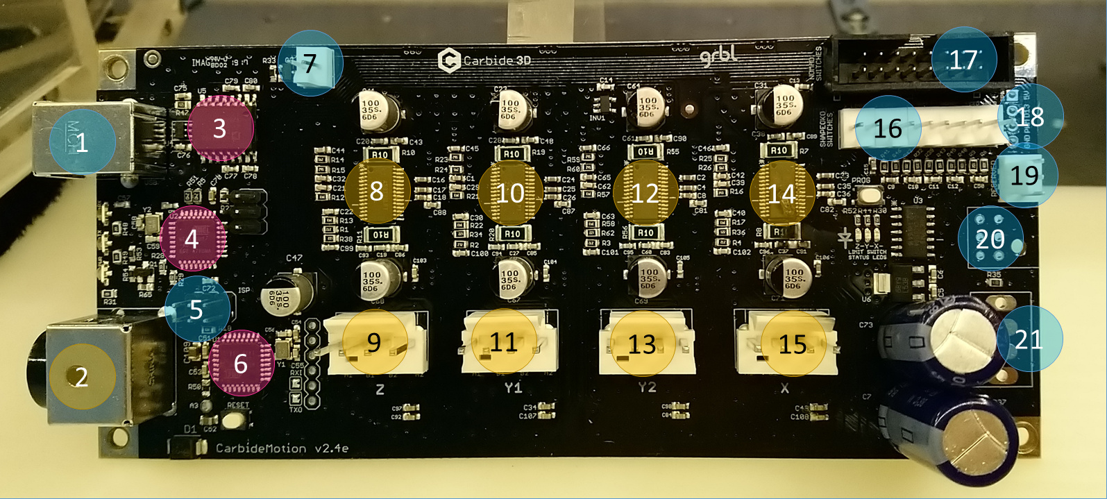
for PWM: what @fenrus said, or at location #18 (but requires to solder a pin header, which is easy to mess up, don’t ask how I know…)
1 Like
Hi Julien, on #21 on your picture what is that for?
I’ve seen that it has to do with power but when I talked to support they said don’t use it.
I’ve wanted to get rid of the brick and put in a standard power supply.
Thanks,
Jeffery
#21 is “24V AUX” and “AUX ON/OFF”, but apart from that I can’t add anything useful, sorry. If support said don’t use it, they may have their reasons.
1 Like
With AUX I wonder if it’s an output, not an input.
Thanks Julien
I made the mistake of hooking up the Bit zero and BitSetter up to those ports. No damage but the BitZero did not work properly. You have to use the little board. I wrapped the board with tape for belt and suspenders.
1 Like
This topic was automatically closed after 30 days. New replies are no longer allowed.