Quantifying Modifications

Starting to think I should have gone thicker than 1/2" on my aluminum plate. If it’s a problem, maybe ten revisions down the road, a a cheap idea could be to find orphaned linear rail and bolt it to the bottom. I don’t imagine they otherwise make cheap precision-ground mini I-beams…

I’m otherwise disinclined to brace from beneath, as you’d end up with bowing in the other direction (though with support and dampened), and one of my primary near-term objectives is to get full use of a threaded table, and I’m looking to start using coolant. Threaded inserts get full of schmoo already, as is. But harbor freight is cheap and maybe I’ll do so just for testing purposes.

I am not trying to rain on your parade but measuring accuracy on a CNC below $5000 is like testing a cheap Harbor Freight tool. How ever I will be awaiting your results, it should be interesting!

One could just as easily say that measuring anything on a CNC priced below a Mori is also pointless.

I think we can improve a lot from where we are, without increasing cost and effort too much. We optimize this journey through measurement and quantification. I’m looking for the best path towards “better”:

  • We have brilliant minds finding new ideas, but sometimes they aren’t quite able to express the magnitude of the improvements. One of the sand fill threads, for example, interests me, but to date, nobody cursed with nerdiness as I am has tried to quantify how much it might improve things. So it remains as a “I think it’s better” for now.
  • Also, extending the sand discussion, we don’t know if there’s a minimal amount needed. Maybe there’s a maximum amount that starts hurting the system’s performance? What’s the optimal? Epoxy granite is a much bigger pain in the ass, but is the result worth it? Without measurements, we don’t know.
  • Some folks are getting fantastic results from linear rails, but how much better? Can you get most of the effect (or even a positive effect) with harder wheels instead? Wheels would be a LOT cheaper and easier, if they gained most of the advantages. Nobody’s tried and measured, to my knowledge.

Already I’ve been able to make mostly-usable (though presently ugly) aluminum parts from a machine that others say cannot do so effectively. I look at @BartK and his work , or @Vince.Fab and his, and am impressed at the potential. Motivation enough.

4 Likes

Bob

Not trying to rain on your parade I should have kept my thoughts to my self. I’m converting my S3 to a Centroid Acorn rev 4 controller because I found the free software though good far behind where I am at these days. This upgrade will allow me to get more out of an already good machine.So U go at it friend I’ll be looking forward to your findings.

It is surprising that Carbide never added a foot/support in the middle since it would be a inexpensive fix/improvement to make.

4 Likes

Say no more, fam, I gotchu (but primarily me, as a proof of concept):


centerbrace.c2d (14.1 KB)

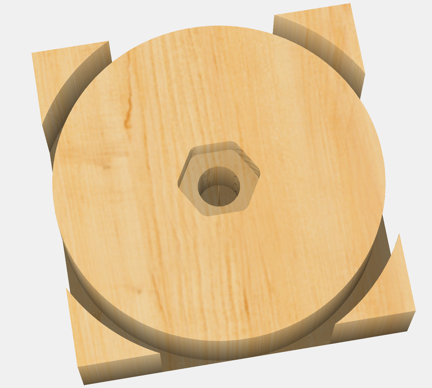
Designed to use 1/4-20 nut and bolt. Something like a 1" bolt will work on mine, and I’ll hot glue or epoxy in a nut and vibratite the bolt on.

5 Likes

Filling extrusions with sand certainly helps as it makes your cnc heavier. Weight helps so anything you can do to make it heavier will work. My diy cnc is built using openbuilds extrusions and wile theyre greatly inferior compared to the C3d extrusions I’ve filled them all with as much steel rebar and epoxy as I could fit inside. Machine became probably 3 times heavier. It’s more rigid and the weight helps counteract vibrations. Believe this would be a great way to improve so3’s performance. Way better than sand imho and I did try both options.

Regarding the use of linear rails. They make enormous difference! I’ve never updated the ‘so3 on steroids’ thread but surface finish is day and night difference. I used to cut aluminium on standard so3 with v-wheels and steel-core belts and while the results were decent and edges fairly smooth to the touch (with visible chatter marks) - now they’ve mirror like finish. Couldn’t be happier with all the upgrades I did to the so3.

5 Likes

You are not alone, I’ve seen posts here from several people doing something similar and I remember particularly @Vince.Fab who did the same by filling the extrusion with sand I think. Some people reported using special sand with polymers. A quick search of the forum should identify several.

1 Like

I studied your build a lot, and it seems really only the big extrusions remain from the original machine. If you were to give your intuitive sense of what improved your machine the most (by whatever metric), what were your top three upgrades?

1 Like

Some folks are getting fantastic results from linear rails, but how much better? Can you get most of the effect ( or even a positive effect ) with harder wheels instead? Wheels would be a LOT cheaper and easier, if they gained most of the advantages. Nobody’s tried and measured, to my knowledge.

One of the advantages of linear rail is reduced risk of schmoo/chips binding the axis. Wheels would require some enclosure and wipers to take on the full advantage of linear rails - beyond the other aspects

1 Like
  1. Z axis with linear rails and ballscrew. Whether you’ll buy HDZ or decide to build your own, imho it’s a must if you’re planning on cutting aluminium efficiently.
  2. linear rails. I can’t imagine having any of my machines run on v-wheels anymore.
  3. making your machine heavier - fill the extrusions with sand, pebbles or steel and epoxy. Build a sturdy metal base for the machine and bolt it down to it. It’s incredibly important to have a very solid table. I wouldnt use wood ever again.

Also swap the original belts to the steel-core ones. Ohhh I can’t stress it enough what a difference it made for me when I was first cutting aluminium end-plates for my DIY cnc on the shapeoko.
Besides that, upgrading to the proximity sensors is a must.

All the above mods made the biggest impact to the quality of my cuts. If youre on a budget, replace the belts, z axis, limit switches, fill the extrusions and you’ll see a massive improvement. Adding linear rails is certainly worth the effort but so easy to screw something up.

Check this thread out. XZero CNC The machine doesn’t exist anymore, but pay attention to the components used to understand how important it is to use certain parts over the others.

7 Likes

FWIW, I made similar deflection measurements with a HDZero (Luke’s project before joining Carbide, based on v-slot extrusions, linear rails, and ballscrews).

Over a 1.5m gantry (substantially larger than an XXL), I saw ~60 microns of deflection with a 5 lb weight. That’s 2.3 thou, or around 1/3rd of unllama’s measurements with half of the weight.

3 Likes

You might want to consider applying the forces where they originate (at the end of the cutter) and measure the deflections there. My 2 cents on vibration damping (post 494).

1 Like

So if I understand your post there correctly, you don’t think increasing mass in the case of epoxy granite will help, but how do you feel about varying loss coefficient and damping effect? I’m kind of inclined to generally look at the vibrational world from a mass-spring-damper perspective, and I see the extrusion fills as touching on all three.

I’ll definitely be measuring at the cutting tip - Linear gantry deflection is preliminary but necessary. I would like to deconstruct the impact of individual modifications, and I view tip deflection largely as the end product of a combination of translational and rotational deflections (very roughly, gantry vs spindle/cutter/mount).

1 Like

Gameplan right now looks like:

Configurations Cost
Stock “sorta” tightened belts $0
Calibrated tightness belts $0
Center support $2
Steel belts $10
Harder V-Wheels $50
Filled Extrusions $50
HDZ $400
Linear Rail - X Axis $150
Linear Rail - Y Axis $300

To be evaluated against:

Metrics Confidence I know WTF I’m doing Corresp. Uncertainty
Gantry deflections 100% 0%
Bed weight deflections 100% 0%
Vibration characterization 60% 40%
Cutter deflections 80% 20%
Repeatability 10% 90%

(^^^^ These need to all be 100% before I start the hard-to-reverse mods like V-wheels and filling extrusions)

"Value at Risk" - where am I losing out on the most if I deploy now
image

Hoping to see next week if I can finish up my vibration characterization metric/protocol, and I think cutter deflection is a matter of sitting down and doing it.

There’s another metric I’m trying to get my head around. Who’s got some ideas on how to evaluate “repeatability”, and what that means? Accuracy, precision, RTZ? Maybe I mill out and measure a circle-diamond-square? If we are to evaluate different homing switches in the future, how do we discern the improvement there?

6 Likes

For repeatability, a good test ought to be milling a part such as a circle-diamond-square with a finishing pass, then milling it again, but afterwards, re-homing and then re-running the finishing pass — if the parts measure the same, then repeatability should be quite good — any difference should be attributable to either a deviation when homing, or other movement.

I suppose for best results do it 3 times:

  • initial part
  • initial part and a second finishing pass
  • initial part, rehoming, then second finishing pass
4 Likes

Do you intend to characterize vibration characteristics at machine resonances (too?)? Will you be limited to forcing frequencies below (and forces above) what people typically would/should experience because of measurement bandwidth limitations? Do you intend to measure and document cutting power and details of the cutting parameters (all of those in the SFPF calculator as well the spindle stick-out and test location X,Y, and Z)? Will you be recording audio, video, and calibrated sound pressure levels during your tests? Will you try to determine, address, and evaluate biggest “bang for the buck” modifications first?

As shown here, poor quality spindles can be another vibration source. It’s producer also has a series of videos on building a granite CNC machine,

2 Likes

Just throwing this out there. Of all the mods ive done… the best one was tightening the nut behind the wheel.

The frequency and resonance bubble is super interesting once you dive in. Excited to see what kind of data you find

3 Likes

The nut behind the wheel? The v-wheel nuts?

I think filling the Y extrusions might be OK since they don’t move. I don’t think increasing the mass of the X extrusion would be helpful since it’d take more energy to accelerate/decelerate it.

1 Like