I bought ADXL345 and LIS3DH accelerometers this weekend. We’ll see what makes more sense. While I used plenty of Audacity in school, I never really liked having to shoehorn voltage ranges into acceptable mic voltage ranges, and mic/piezo only gets me 1D info as @gmack alluded to. The MEMS accelerometers offer simultaneous 3D acceleration, which, with a brain twice the size of mine, could yield higher insight.
I also have a stretch goal of trying to produce an arduino-based FFT analyzer that I could use to fine-tune my intuitions about chatter.
In deflection-land, doing some initial testing, it looks like I need a new stand for my dial indicator (well, the stand is ok - the arms/articulation are trash). Despite this, I’ve started playing around and found about 0.004" of deflection in the gantry alone in the -Y at 10 lbs (measuring at the beam, not the spindle! Like 8 inches right of the SHAPEOKO logo). I guess that’s the sum total of V-wheel compression, belt slack/elasticity, and beam deflection, which seems fair, but at the same time surprising to me - I would have expected less on what is intuitively the sturdiest axis. I’m going to resolve the stand arm situation and report back.
I would stress the machine in a few different directions to seat all components into place.
Then make final adjustments on the wheels and belts and such to ensure there’s no play.
You could create a basic program to warm up the machine - common practice on larger CNCs.
Even a 10 minute cycle time moving the spindle all around the bed at RPM will help rather than cold.
Get the components up to temp and they will tighten up a bit in relation to each other.
I also picked up an ADXL345 this weekend, and I’m planning on wiring it into a Raspberry Pi 4, which should have more than enough CPU for doing FFTs. And, more importantly, is easier to grab data off of than an Arduino. It’ll probably take me a while to get around to anything useful, though.
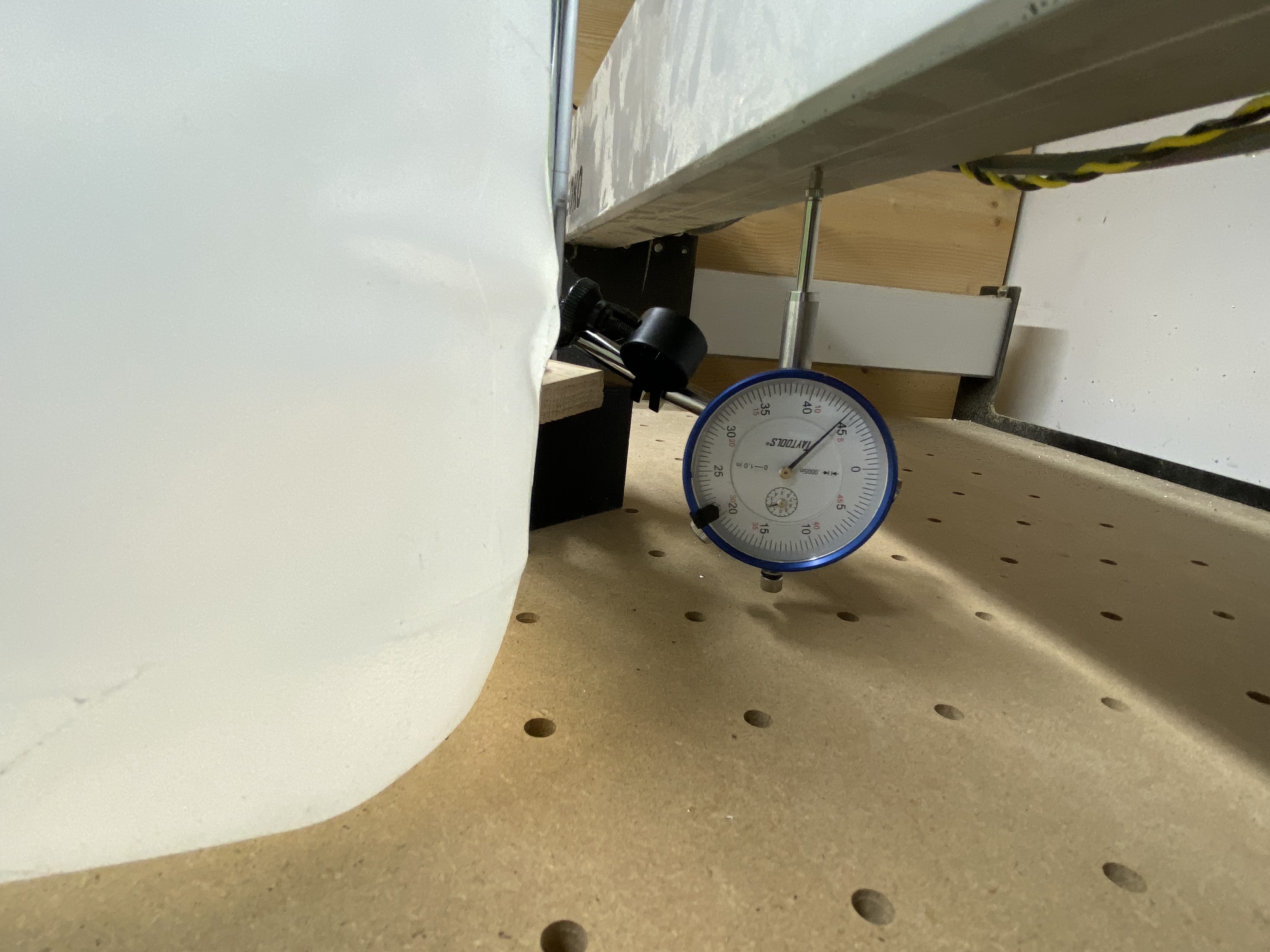
Revisiting deflection today with a slightly better setup (cleaned shipping oil from dial indicator arm)
Setup: Shapeoko 3 XXL, stock belts tightened to 10 in-lbs, 40 degrees F ambient, stock MDF baseboard with threaded inserts in 2" grid and 1/2" sacrificial MDF spoilboard on top.
Testing the center-of-beam movement with 10 lb deflections in the -Y (pulling towards me, standing in front)
Spindle at “NE” on Rapid position (back of machine): 0.005" deflection, return to zero each time (tested 5x)
Spindle at “E” on Rapid position (Middle of Y axis): 0.008" deflection, returned to 0.0015" (was able to push back to zero) for four runs, 0.0085" deflection, returning to 0.002" (able to push back to zero) once
Spindle at “SE” on Rapid position (Front of machine): 0.007" deflection, returning to 0.002" (able to push back to zero), tested 5x
So this is exciting. Just testing translational stress, we’re at 8 thou on the strongest/stiffest axis with a 10 lb deflection load. I had expected to see the deflections get worse at we approached the front of the machine (longer belt length being stretched?), but that wasn’t the case. Also surprised that the deflections would “stick” to some small extent (except at the back of the machine). To be continued with more datapoints, hopefully with warmer temperatures.
Horizontal deflections vs my wasteboard mounted indicator are surprisingly sensitive to pressures applied to the wasteboard. As a side test, a calibrated gallon of Great Value drinking water weighing 8.68 lbs placed ~center of wasteboard induced a -Z deflection in the wasteboard of 0.006" (measured relative to gantry)
The topic of wasteboard sagging in the middle (under its own weight and when pushing on it when e.g. using the tape and glue method) comes up regularly, especially on XXLs, so I would not be surprised that in terms of bang for the buck, any kind of mechanical reinforcement under the middle area of the wasteboard will appear at the top of your list. Aluminium beds will be there too, but considering the price I expect they will show up much lower in the list.
Starting to think I should have gone thicker than 1/2" on my aluminum plate. If it’s a problem, maybe ten revisions down the road, a a cheap idea could be to find orphaned linear rail and bolt it to the bottom. I don’t imagine they otherwise make cheap precision-ground mini I-beams…
I’m otherwise disinclined to brace from beneath, as you’d end up with bowing in the other direction (though with support and dampened), and one of my primary near-term objectives is to get full use of a threaded table, and I’m looking to start using coolant. Threaded inserts get full of schmoo already, as is. But harbor freight is cheap and maybe I’ll do so just for testing purposes.
I am not trying to rain on your parade but measuring accuracy on a CNC below $5000 is like testing a cheap Harbor Freight tool. How ever I will be awaiting your results, it should be interesting!
One could just as easily say that measuring anything on a CNC priced below a Mori is also pointless.
I think we can improve a lot from where we are, without increasing cost and effort too much. We optimize this journey through measurement and quantification. I’m looking for the best path towards “better”:
We have brilliant minds finding new ideas, but sometimes they aren’t quite able to express the magnitude of the improvements. One of the sand fill threads, for example, interests me, but to date, nobody cursed with nerdiness as I am has tried to quantify how much it might improve things. So it remains as a “I think it’s better” for now.
Also, extending the sand discussion, we don’t know if there’s a minimal amount needed. Maybe there’s a maximum amount that starts hurting the system’s performance? What’s the optimal? Epoxy granite is a much bigger pain in the ass, but is the result worth it? Without measurements, we don’t know.
Some folks are getting fantastic results from linear rails, but how much better? Can you get most of the effect (or even a positive effect) with harder wheels instead? Wheels would be a LOT cheaper and easier, if they gained most of the advantages. Nobody’s tried and measured, to my knowledge.
Already I’ve been able to make mostly-usable (though presently ugly) aluminum parts from a machine that others say cannot do so effectively. I look at @BartK and his work , or @Vince.Faband his, and am impressed at the potential. Motivation enough.
Not trying to rain on your parade I should have kept my thoughts to my self. I’m converting my S3 to a Centroid Acorn rev 4 controller because I found the free software though good far behind where I am at these days. This upgrade will allow me to get more out of an already good machine.So U go at it friend I’ll be looking forward to your findings.
Filling extrusions with sand certainly helps as it makes your cnc heavier. Weight helps so anything you can do to make it heavier will work. My diy cnc is built using openbuilds extrusions and wile theyre greatly inferior compared to the C3d extrusions I’ve filled them all with as much steel rebar and epoxy as I could fit inside. Machine became probably 3 times heavier. It’s more rigid and the weight helps counteract vibrations. Believe this would be a great way to improve so3’s performance. Way better than sand imho and I did try both options.
Regarding the use of linear rails. They make enormous difference! I’ve never updated the ‘so3 on steroids’ thread but surface finish is day and night difference. I used to cut aluminium on standard so3 with v-wheels and steel-core belts and while the results were decent and edges fairly smooth to the touch (with visible chatter marks) - now they’ve mirror like finish. Couldn’t be happier with all the upgrades I did to the so3.
You are not alone, I’ve seen posts here from several people doing something similar and I remember particularly @Vince.Fab who did the same by filling the extrusion with sand I think. Some people reported using special sand with polymers. A quick search of the forum should identify several.
I studied your build a lot, and it seems really only the big extrusions remain from the original machine. If you were to give your intuitive sense of what improved your machine the most (by whatever metric), what were your top three upgrades?
Some folks are getting fantastic results from linear rails, but how much better? Can you get most of the effect ( or even a positive effect ) with harder wheels instead? Wheels would be a LOT cheaper and easier, if they gained most of the advantages. Nobody’s tried and measured, to my knowledge.
One of the advantages of linear rail is reduced risk of schmoo/chips binding the axis. Wheels would require some enclosure and wipers to take on the full advantage of linear rails - beyond the other aspects
Z axis with linear rails and ballscrew. Whether you’ll buy HDZ or decide to build your own, imho it’s a must if you’re planning on cutting aluminium efficiently.
linear rails. I can’t imagine having any of my machines run on v-wheels anymore.
making your machine heavier - fill the extrusions with sand, pebbles or steel and epoxy. Build a sturdy metal base for the machine and bolt it down to it. It’s incredibly important to have a very solid table. I wouldnt use wood ever again.
Also swap the original belts to the steel-core ones. Ohhh I can’t stress it enough what a difference it made for me when I was first cutting aluminium end-plates for my DIY cnc on the shapeoko.
Besides that, upgrading to the proximity sensors is a must.
All the above mods made the biggest impact to the quality of my cuts. If youre on a budget, replace the belts, z axis, limit switches, fill the extrusions and you’ll see a massive improvement. Adding linear rails is certainly worth the effort but so easy to screw something up.
Check this thread out. XZero CNC The machine doesn’t exist anymore, but pay attention to the components used to understand how important it is to use certain parts over the others.
FWIW, I made similar deflection measurements with a HDZero (Luke’s project before joining Carbide, based on v-slot extrusions, linear rails, and ballscrews).
Over a 1.5m gantry (substantially larger than an XXL), I saw ~60 microns of deflection with a 5 lb weight. That’s 2.3 thou, or around 1/3rd of unllama’s measurements with half of the weight.
You might want to consider applying the forces where they originate (at the end of the cutter) and measure the deflections there. My 2 cents on vibration damping (post 494).
So if I understand your post there correctly, you don’t think increasing mass in the case of epoxy granite will help, but how do you feel about varying loss coefficient and damping effect? I’m kind of inclined to generally look at the vibrational world from a mass-spring-damper perspective, and I see the extrusion fills as touching on all three.
I’ll definitely be measuring at the cutting tip - Linear gantry deflection is preliminary but necessary. I would like to deconstruct the impact of individual modifications, and I view tip deflection largely as the end product of a combination of translational and rotational deflections (very roughly, gantry vs spindle/cutter/mount).