Hey guys, I’m a high performance automotive Fabricator and use my S3 pretty much daily and am setting up a second. I’ll update this thread with cool aluminum milled parts
Many more parts and setup photos can be seen on my instagram @Vince.Fab
Hey guys, I’m a high performance automotive Fabricator and use my S3 pretty much daily and am setting up a second. I’ll update this thread with cool aluminum milled parts
Many more parts and setup photos can be seen on my instagram @Vince.Fab
Welcome, Vince! Looking forward to your posts!
impressive! Mind sharing your work holding and work flow setup?
Thank you! I through bed mounted a 6" cnc vise with fabricated frame. Using Fusion 360 on all 3d parts, still carbide create on simple 2d.
I use 3/8s to 1/4 carbide bits, roughers with chipbreakers then ball finish.
awesome! How long did the milling portion take?
Thanks! These were the first two prototypes so cam was still being dialed in. Crash free I’m looking at 6 hours per part with double sided machining and a 10 thou finish pass on all surfaces. Part goes from a 10 lb block to a little under 1lb
Are you able to recover that 9 lbs of aluminum chips and either recast them or sell them back to an aluminum recycler?
Great work! What type of coolant do you use? What spindle is that and what RPM do you run it at? So many questions… 
Unfortunately right now they just get swept up and tossed. Even if I was producing barrels full it doesn’t recycle for much, if even worth the trouble.
Thank you! Im still learning everyday. I run 100% water due to cleanup issues and tig welding. Mostly 20-25k rpm. I run a bone stock Makita, runs pretty cool even above 20k, been cutting over a year on it.
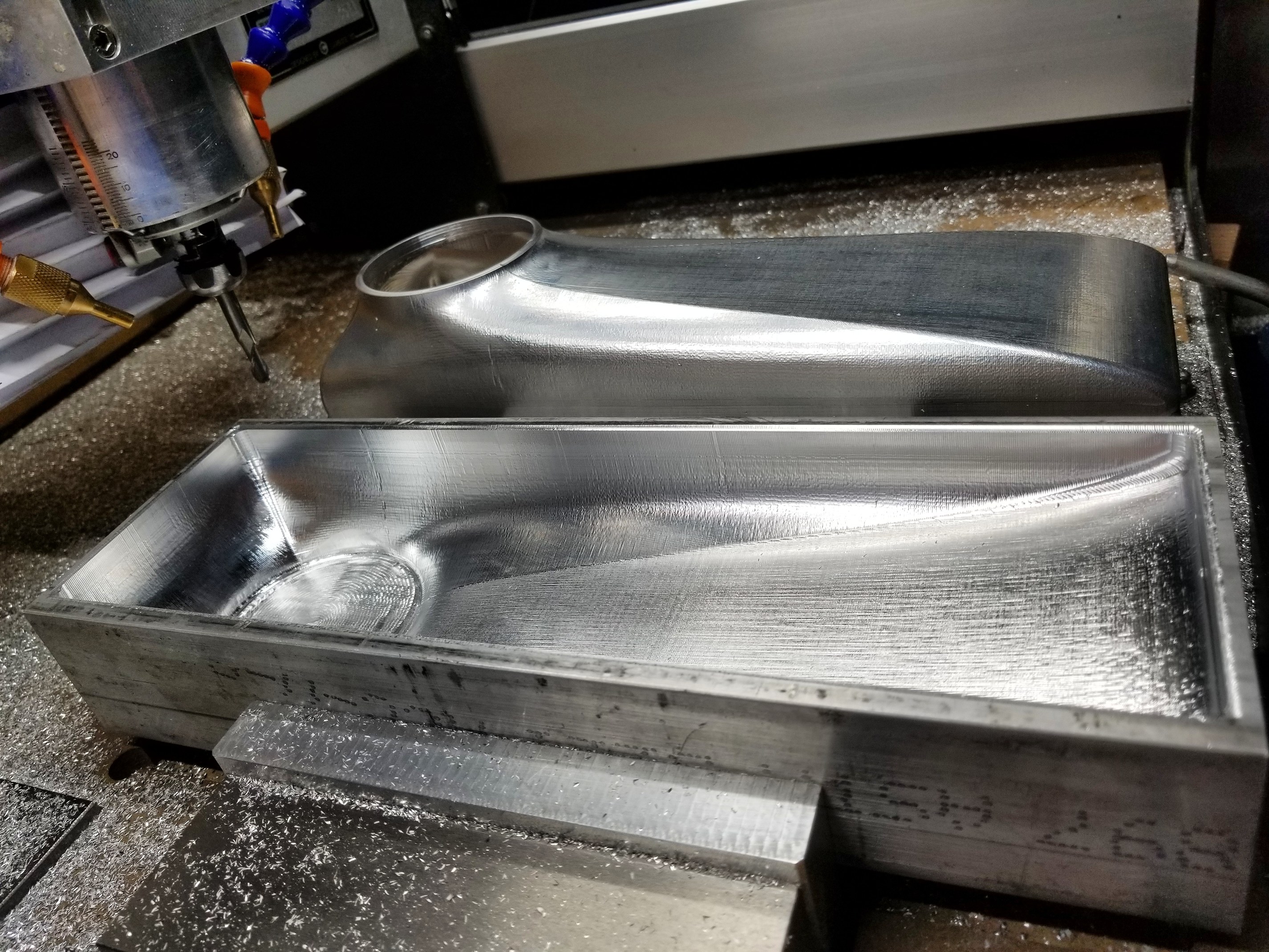
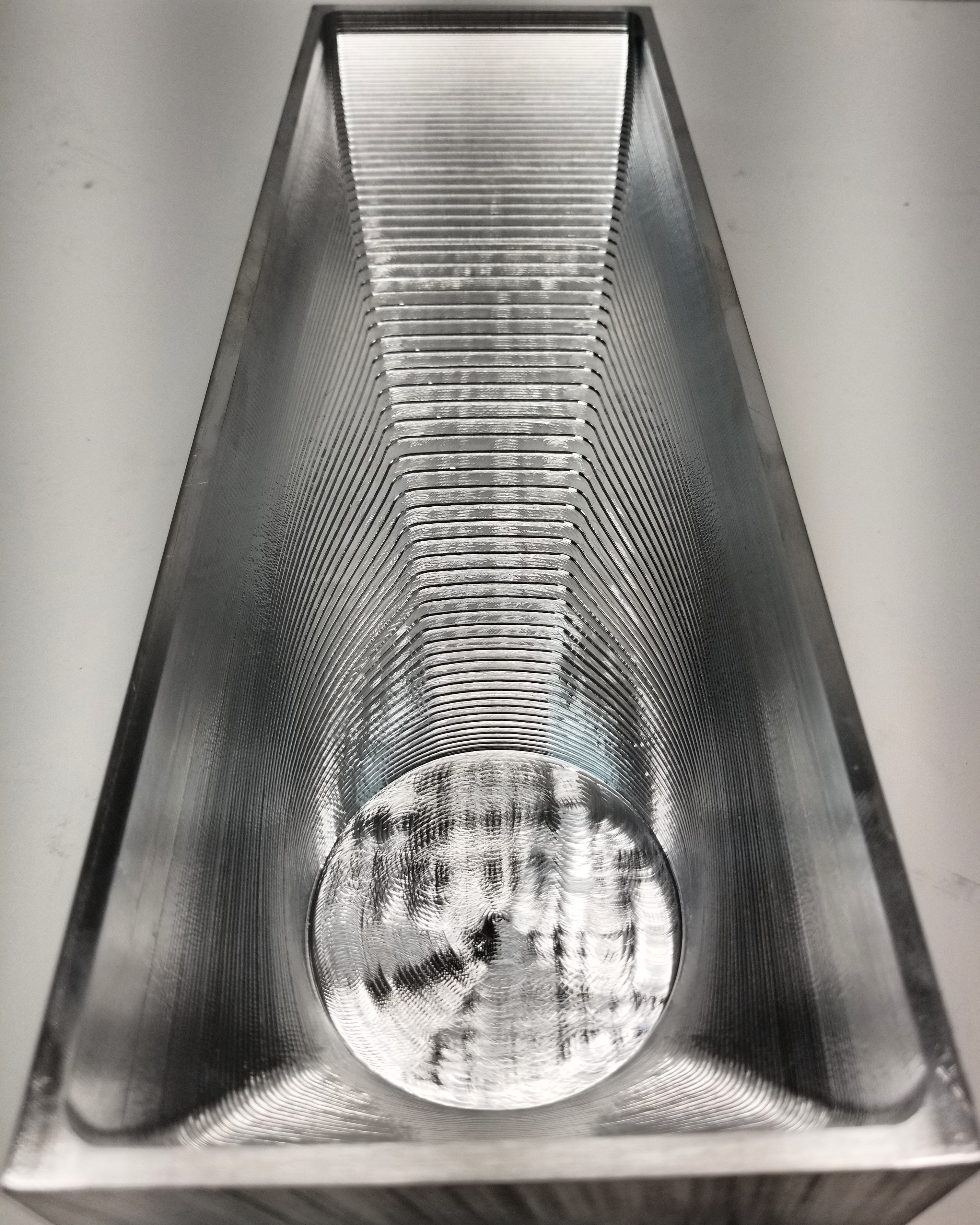
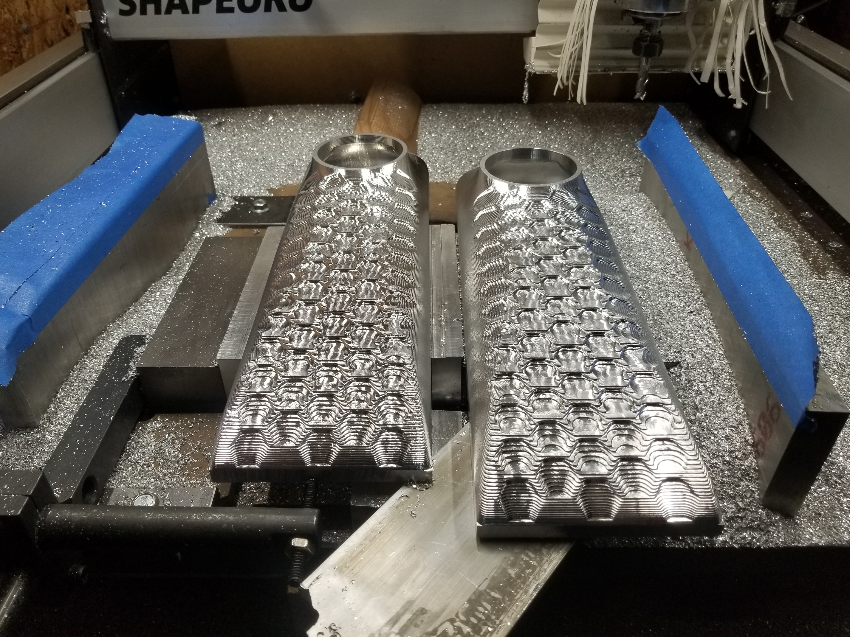
Right now my metal removal rate is about 2lb per hour  Heres some roughing from today
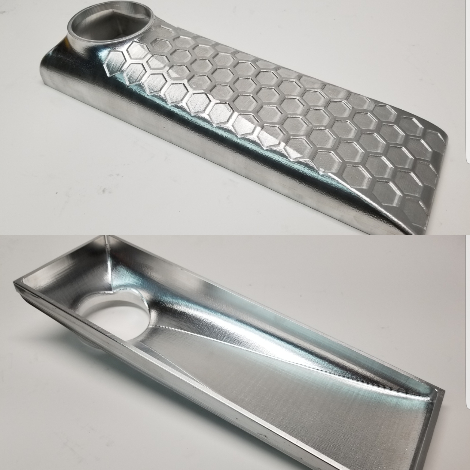
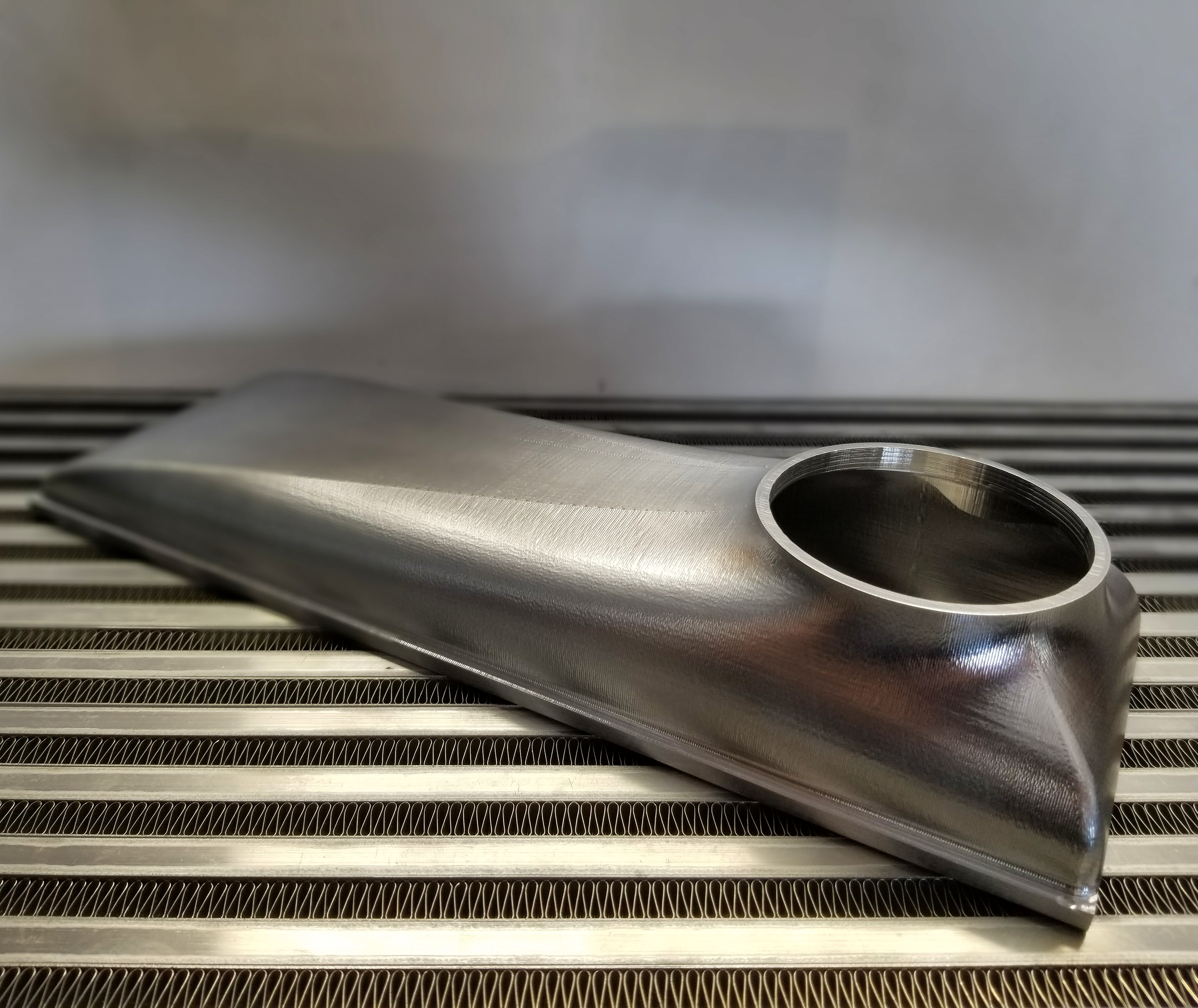
One day and 18lb of metal removed, that’s a record for me lol. These intercooler endtanks are for a 750 hp road race car and I have redesigned them to be super light weight and high stiffness. They dropped about 25% mass compared to my high boost 60+ psi ones.
I love machining! If you have the time and drive you can make anything!
Today I’ll be doing finishing operations but my computer is having trouble computing rest machining on adaptive cutting stepping sizes. Gotta make more money to buy a better computer!
I love watching your creations.
How are you ensuring the parts are in the same place when you do the flip?
What kind of tolerances are you working too? Mind sharing a fusion 360 file so I can take a look at your tool paths?
Every part has it’s own cool lesson.
You can see the vise stop in the photo. I locate off the center end for the flip and reset it lower for the 2nd op for tool clearance. I’ll recheck with calipers but its within a couple thou every time.
The thinnest sections on this part are 0.100 and my acceptable tolerance is plus or minus 5-10 thou.
Unfortunately I do not share production part files but I can make a sample with toolpaths if you like
do you have some sort of custom baffle design to keep the chips out of the Z-axis?
Yes sir. I try all kinds of things to see what works for extreme use. These are a quick set made from a window airconditioner spacer, plastic and coolant/heat friendly.
I haven’t had a chip single Z related failure since installation. Cost $12
Chip issues are also influenced by the type of cutters you use and style to use them. Parts can be oriented in certain ways to protect rails from debris as well.
It is just a brutally computationally intensive task, and it doesn’t parallelize well, apparently. A bit of creativity can really help, though. A faster machine helps, but not as much as one would think. My recent upgrade (lightning strike was my path to upgrading…) was a machine with 3X the memory, twice the hard drive, and about 10X the GPU of the old one, 1.5X clock (but the same 4 cores) gave me about 50% gain on toolpath computation.
On the external surface (convex and low curvature concave), I wouldn’t bother with selecting rest machining. If you left, say, 0.25mm (0.010") nominal, and the roughing step down is 0.5mm, then the max left to cut is 0.75mm. Just run a pass with the ball using your strategy of choice as a finish. It will probably run faster, and definitely compute faster, as the rest machining will give a more involved path.
One thing I have learned with Fusion and Inventor (same CAM engine, substantially) is that if it is taking too long to compute, I need to revise my specs, as it is probably going to be a tool path that is too complex to be efficient. There are exceptions (like the example I ran the other month for the rope detail on a surface), but they are rare. Often, careful selection of top and bottom planes makes a huge difference, and selecting a different strategy for the excluded part (if needed… sometimes you can exclude the part that is taking forever as it is already finished) will give faster computation and more efficient toolpaths.
That is some beautiful work! Custom work for my own cars is a large part of what I bought my XXL for… AS with many who post here, Highly inspirational!
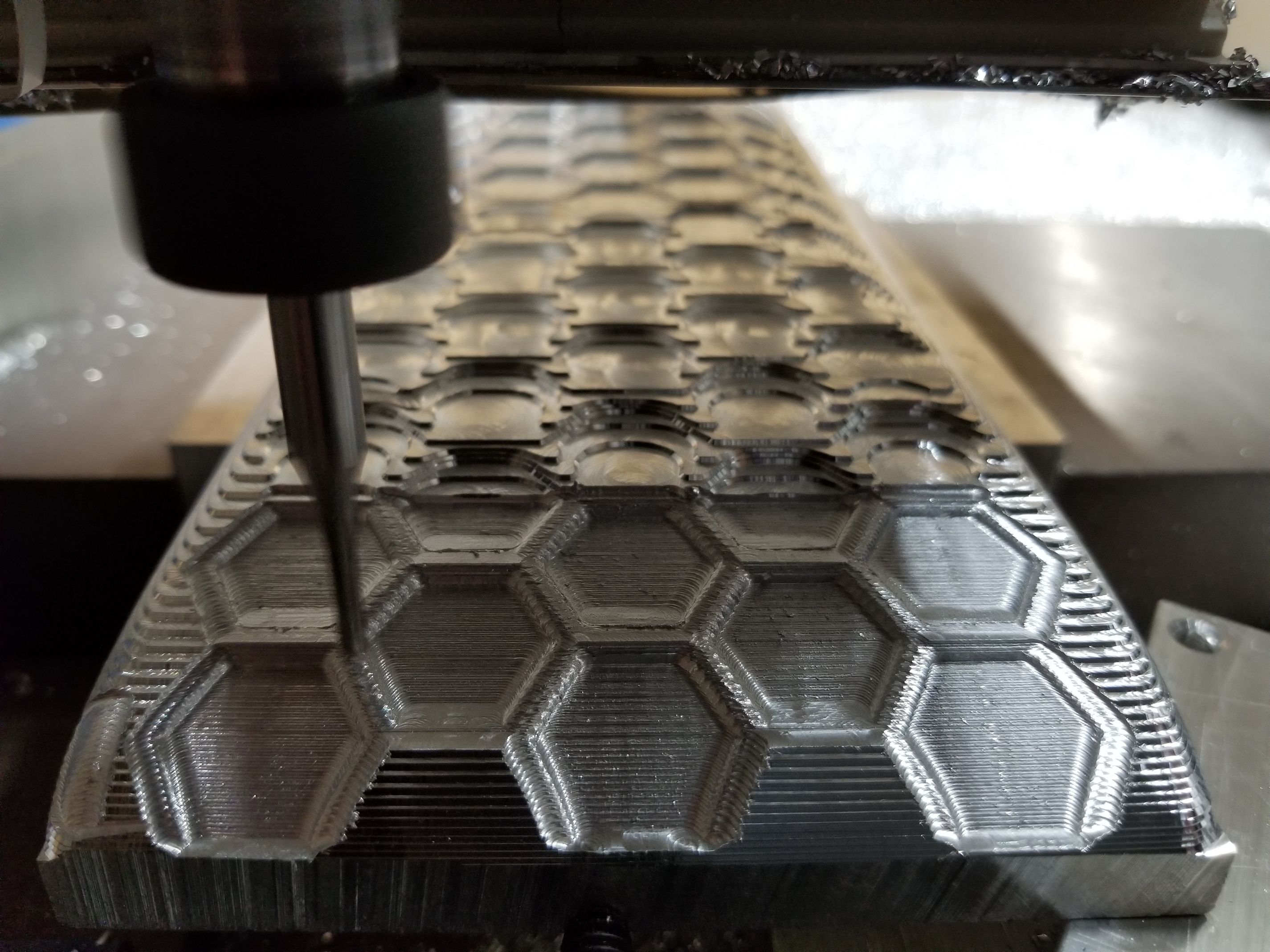
You hit the head right on the money on complication! I actually split that toolpath into five different sections and was running it but while figuring out contour finish paths it clicked. I decided to run a contour path on just the hex pattern with rest machining with a 0.125 square because I didn’t have a ball smaller than 0.250. Then I’ll run the ball over the outside and avoid the hex for hopefully good looking toolpaths. Thanks for the tips!