which photos ? :)⠀⠀⠀
Yup that’s what I thought @carguy84 was going for. But he’s going to need a plug, like your foam core, for that. And enough space to get compaction when it’s together. It’s a great approach, but he needs to remember to make the plug.
If you’re talking about the process that I think your talking about then yes, this is hands down the best way to do it. You’re thinking of a biaxial sleeve with a bag in it, open to atmosphere, and then an outer bag around the mould with vacuum, correct?
1 Like
Exactly, the second bag would act as the plug and be able to seal against the inside of the mold. You seal the outer bag around the 2 molds and the inner bag goes “through” the outer bag open to the atmosphere.
Sorry for missing the link earlier:

Chip-
2 Likes
Allright, I may have a lead. Your STL rendering / 2nd pic shows this :
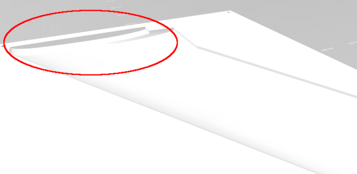
The picture is too white to see exactly what is going on there, but the same STL imported in Fusion gives this:
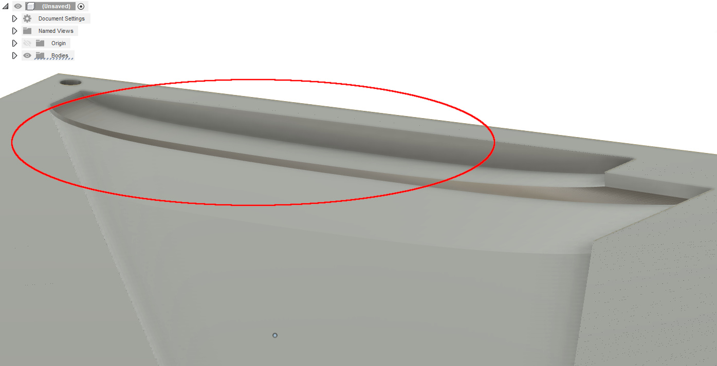
which looks consistent with CC’s interpretation:
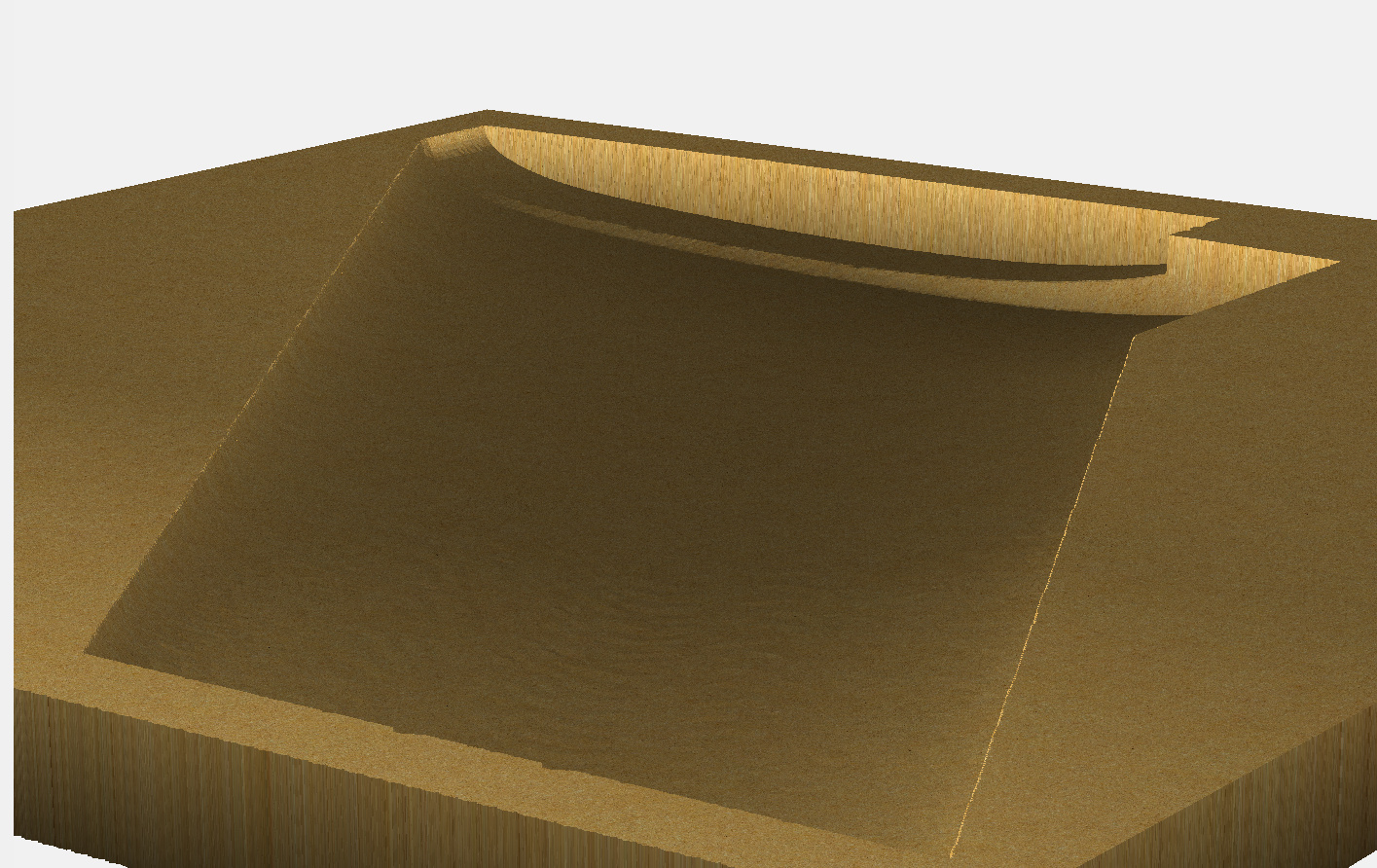
Now, I wonder if it’s only a matter of Z scaling:
- the native STL file has a modeled height of 10.27mm /0.4", and the wing itself does quite not use that full height, so let’s say it’s actually 0.35" thick
- I’m not sure how @fenrus’s tool works but I would assume it maps STL height as [0-255] corresponding to the [min height as seen from projection angle - max height as seen from projection angle]
- If you then used the generated heightmap in CC, the [0-255] will scale to whatever height you specified in the 3D shape in CC when importing the heightmap: any height greater than 0.4" will “stretch” the model along Z axis, compared to the original STL ? Hence making those walls on the trailing edge “higher” than in the original STL ?
- If I recreate the 3D shape, but select 0.35" as the shape height rather than 0.75" in your original design, I get this:
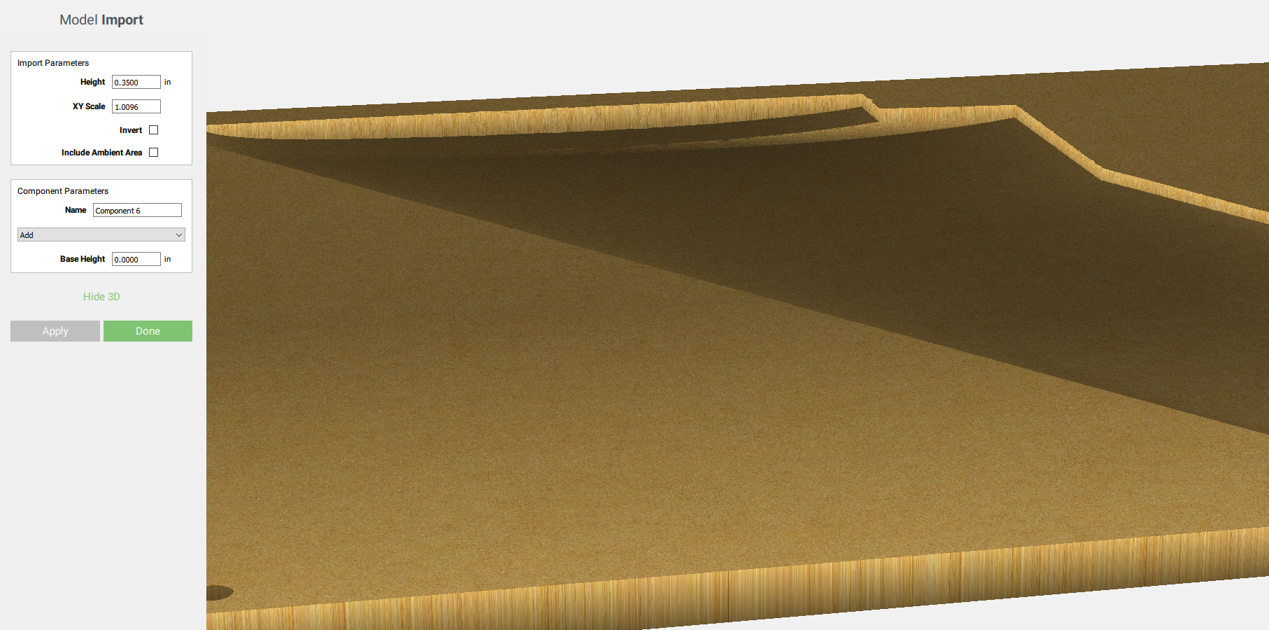
which looks suspiciously like your 2nd pic, and what I guess you expected to see ?
1 Like
one thing the original command line version of the tool did, but the web tool does not yet, is to print various x/y/z sizes to keep aspect ratio
I’ll add that to the web version shortly
1 Like
ahhhh, yup that seems to be exactly what the issue was. I never updated the import parameters for the “shorter” depth the bottom half of the wing came out to be. Incredible sleuthing!
Thank you thank you!
1 Like
@carguy84 Yes, when you do it please post some photos. I’ve been itching to try out that method of layup, and I love to know how your experience is. I plan on doing something similar what you’re working on now, when I get a few more projects off my list. So any documenting you do would be incredibly helpful  .
.
Small update, I finished the CNCing of one half of the wing (to make the sandwich. On to duratecing it and getting it nice and smooth. My plan is to do as much as possible in MDF until I have it how I like it and then use epoxy tooling board.

Chip-
3 Likes
This topic was automatically closed 30 days after the last reply. New replies are no longer allowed.