Hello,
I received my Shapeoko and fortunately have been able to really use it during this quarantine and am REALLY impressed at its capabilities and accuracy. I’m a retired web developer and have been really digging my hands into creating 2D things. Now I’m trying to tackle a 3D project I want to make which is an RC airplane model of a flying wing so I can create it out of carbon fiber. It’s been something I want to do for a while a now and one of the main drivers of me buying a CNC.
I put up an imgur album of the RC airplane, and I have the normal sized Shapeoko so would need to do a left wing/right wing design in order for it to fit.
What I’ve done is first try to make the wing in Carbide Create so that I could at least mimic the design or get it close enough, and then figure out how to make the mold version.
However I can’t figure out a lot of things, like how to make the leading edge, how to get the chord of the wing correct and how to get the shape of the airfoil correct as well. I don’t know how to post the c2d file up directly here so just created a download: https://easyupload.io/r6uhrr
While this is just a hobby of mine, I am more than willing to pay for help on this as I consider it a real skill and more than happy to throw some cash at it. Feel free to DM me about it or post up here any help. And I am happy to share my progress and files along the way in case anyone else wanted to try it out or is also an RC enthusiast who doesn’t want to shave foam!
Doing this completely in CC seems like an interesting endeavour, but generating toolpaths in Fusion360 or MeshCAM (or whatever other CAM program you have access to?) would probably be easier.
Do you have a 3D model of that flying wing ? If so, and if you want/need to use CCPro, you should be able to project each side of the wing do a single greyscale heightmap using @fenrus’s fantastic tool mentioned on this thread:
Thanks for the help! I hadn’t considered using some other software to design it, I’ve downloaded Fusion 360 and I have found some other people’s STL files on the line and will see what kind of progress I can make there.
So I’ve really been having some fun learning here and I can’t thank you guys enough for the direction on all this. What I’ve done so far:
Using the links above, I found an STL project that was close enough to what I was trying to do:
I downloaded the STL2PNG program and ran that on the parts of the plane and then opened it in Create, which is where I learned about the Invert feature to take the male PNG files and turn them into a female mold project.
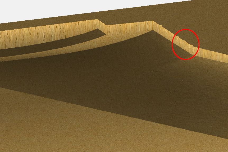
I did the cut, but I only had 3/4" MDF and not 1" and it went through the bottom because for some reason the section of the wing is down like 1/8" from the top of the MDF? You can see it from the last photo on the imgur link above.
Overall I consider it a big move in the right direction, I just don’t know why it’s starting the cut so low.
I don’t know how to post the STL file I used, but it’s at that GASB ONE project above.
I will say it came out way better than my corona DIY haircut…
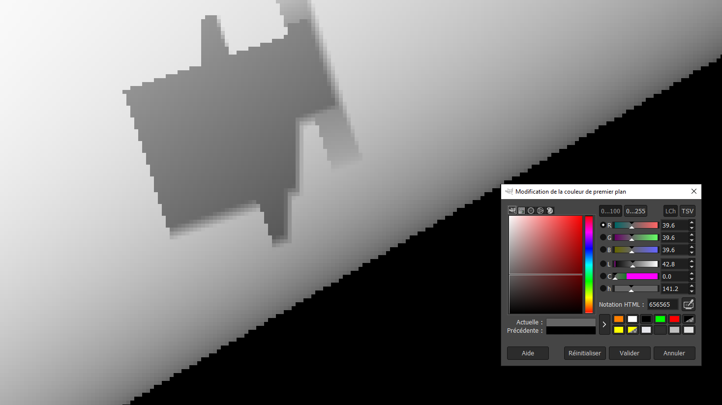
the first non-black pixels on the edge have a value of ~40
The max depth/height corresponds to value 255, so basically CC considers that this step between the black and the grey parts is (40/255)% of the specified thickness, and (40/255) x 0.75" = 0.117", close enough to the 0.125" you see.
You should be able to tune the height and /or base height in CC Pro to compensate ? If not share your CC project and someone here will probably figure out a simple trick.
EDIT: also, :
My first haircut since this thing began is planned for end of next week, with everyone wearing masks and stuff…that will be weird.
Fenrus, I submitted an update for the stl2png html page. Just updated the layout so the last thing you do is select the file since you need to select Top/Side/Front before you select the file anyway. Also did an HTML tidy up and a few user experience updates (added a title, got rid of some syntax errors and added in labels for the radio buttons so you can click on the words too instead of just the radio buttons).
Hi @carguy84, I have not tried carbon fiber or molds for any RC stuff. I’m a balsa and ply builder. Here are some programs I use to help create RC stuff. WingHelper for wing designs. https://www.winghelper.com/default/ and devCad Pro with CAM for general work and parts layout and gcode generation. http://www.devcad.com/eng/default.asp There are other devCad products that maybe of interest to you. As an example you can see this years project in pictures here: https://flic.kr/s/aHsmKq2FFf I used WingHelper, devFus and devCad. Again, this is an all balsa and ply design, but other tools are out there for a price.
I’ll be interested to see what you come up with both as a final product, but also on the tools and materials you use. I have not thought of using a 3D carve for a wing. Making plugs for vacuumed formed parts maybe??? Lots of possibilities! That’s the best part of these machines.
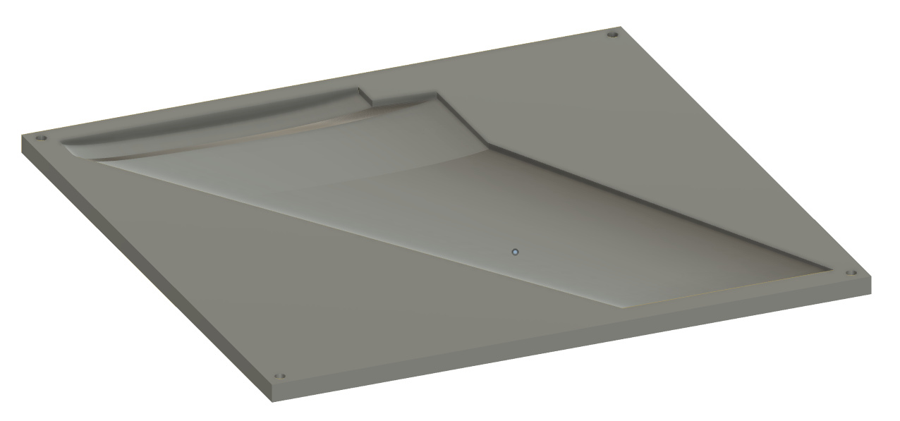
I have made it further now, thank you @SLabuta for the DevCad site! They have a Mold program that really has helped me accelerate a lot of this process now! Here is where I stand now, 3 images from the current progress:
I have the plane designed out, I used the STL to PNG program and have it imported into Carbide Create. On half of the wing mold side it is still dropping the cutout section about an 1/8th or so of an inch and I’d love to figure out of there’s a more direct way to import these STL files into Carbide Create? I tried converting it to an SVG but just ended up with a whole bunch of pink lines.
I’ve come up with a work around which adds an additional cutting toolpath to cut the whole mold down 1/8th of an inch before its run the real toolpath, but that seems like a waste of time and a needless amount of sawdust. I guess I could adjust the Z Axis after I do the probbing? And then I would only be wasting time. But ideally I’d love to come up with a way to better get the STL imported into Carbide Create. Any suggestions would be very welcome!
Thanks again for all your help and guidance so far!
Which matches the generated heightmap when at the leading edge there is a smooth transition from black (depth 0) to lighter grey inside the wing profile:
So it looks like you are fairly far along in this now… I wish I had seen this post before. If you ever go back to Fusion there are a bunch of free addins that let you enter the data for the NACA foil, or just use the .DAT file, and it will generate the wing sketch for you. After that it’s just extrude along a spline and set the curves as rails, if I remember correctly. Once you have the wing model create a new solid block around it with the wing in the center. Then use Combine with the ‘subtract’ option. After that use split body, and boom your golden! Two bodies that are the two halves of the mould. Here is a link to the Fusion addins if you’re interested.
@carguy84 If your going to do it in carbon what was your plan? Make molds, cast a urethane positive, then compression mould? Or were you going to vacuum bag it? I only ask since my buddy and I have quite a bit of experience and if you have questions I’d be more than willing to help.
I have done a similar build 20 years ago with my 1/12 scale air combat wings. I used the resin infusion lost foam approach.
Hotwire cut the foam cores.
Make the spars and stringers out of carbon plates.
Do the cutouts for spars and stringers in the foam cores and glue them together.
Wrap the foam assemblies with the fabric and vacuum bag them.
Infuse the resin and let cure, de-bag and dissolve the foam with gasoline.
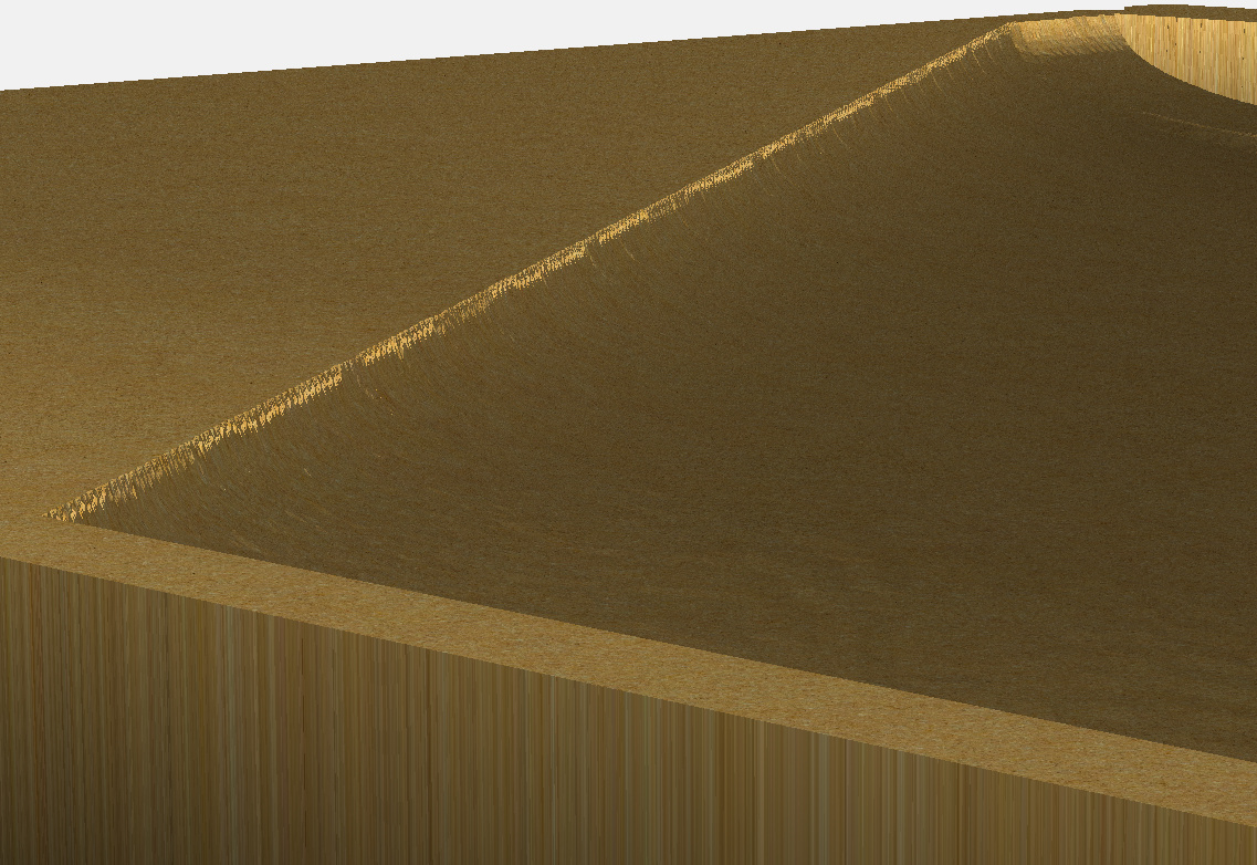
@fenrus@Julien For the 1/8th, maybe these 2 photos better show what I am talking about. The first is from Carbide Create when I import the PNG file. The second is direct from the DevMold STL file. You can see the cuts are deeper on the carbide create import than the original STL.
@TheSilentEngineer that pretty much sums up what the DevMold program will do, although some of the items you mentioned are automated in it and it doesn’t do anything else other than this so surely not as flexible (nor complex!) as Fusion. The plan is to make the negative molds and then lay the carbon fiber, put the top and bottom together and then double vacuum bag it.
@BrokenEndmill in that case, did the vacuum bag end up clamping on the outer skin of the airfoil? Similar to what I’m going for here, but I wanted the airfoil to go against the mold to make it as smooth as possible.
The leftover foam from the hotwire cutting was used as a “mold” during vacuum bagging, clamping down on the fabric/skin. Correct use of peel-ply, release film and breather cloth should give a surface with very little work needed before painting.
There should be plenty of videos on YouTube that show the process.


 )
)