It has been a long time since I have posted here. I have continued my CNCing journey but have stopped milling myself. Mainly because of needing larger machines and me not having the money or space for larger machines. I want to replace the controller of my Nomad883 Classic (the first version) with another controller. Probably this:
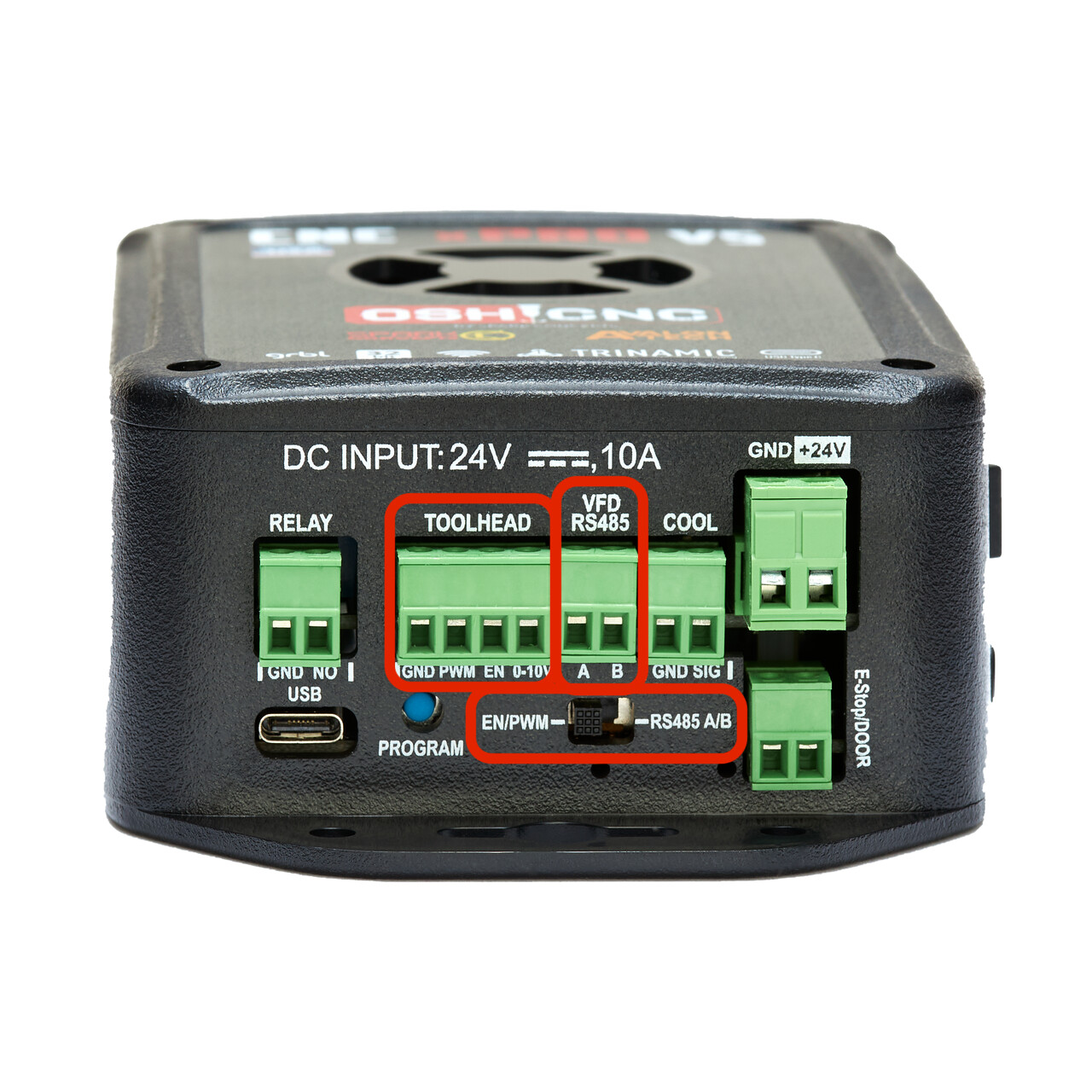
I’d like to still use the spindle controller but need to know if the xPro-V5 controller has what the Carbide spindle controller needs. This is what the xPro-V5 supplies:
Spark Concepts xPro-V5 includes a 0-10v Analog Signal Voltage output that can be used to control spindles/other toolheads that need a 0-10v signal to run.
Note: This is a low level logic Signal voltage, it should not be used to drive anything directly. This signal should be connected to an external drive system, for example a VFD or a DC Spindle Controller.
To use the signal, connect between the GND and 0-10v pins on the toolhead plug as shown.
Is this what the Carbide3D spindle controller needs?. What are the signals in each of the 5 cables that connect the controller to the spindle board?.
I can’t seem to get any info to progress into my controller replacement. I know it can be done as I have seen the posts here of @Moded1952. He seems to not be not present in this forum anymore unfortunately. I have tried to see if I can figure a bit more on my own and this is what I have found:
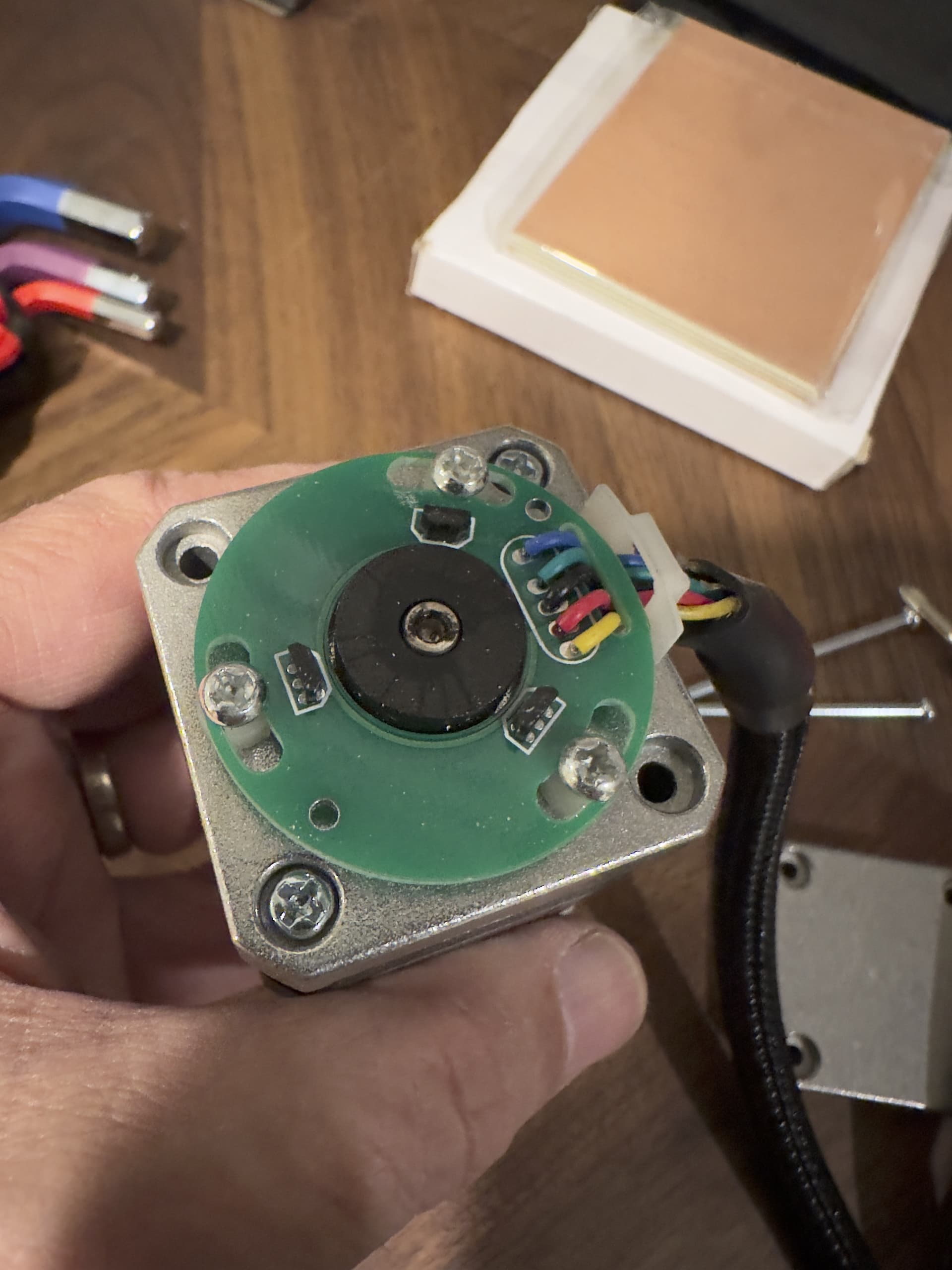
There are five cables connecting the controller and the spindle control board. They are as follows.
Black —— Ground
Red —— 24V
Yellow —— 0-5V (when turning on spindle 0-10000rpms) [PWM?]
White —— Unknown
Green —— Unknown
I only have a multimeter with me so I am only able to measure voltage. Trying to get my hands on an oscilloscope to see the frequency of the 5V signal of the yellow wire.
Does anyone know what the white and green cables might be?.
The xPro-V5 controller seems to have two types of control for spindles.
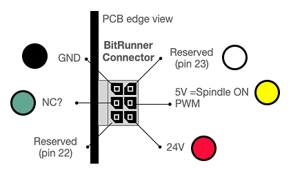
The reason I didn’t respond earlier is because there are answers to all this on the forum already. Search for “Bitrunner pinout” and you’ll find them easy enough.
The Nomad 883 Pro spindle controller at least seems to take 0-5V PWM and your controller seems to output it so electrically this should be fine.
I’m not sure why you’d want to switch to that controller though. You’d be replacing stable, manufacturer-sanctioned GRBL with janky DIY GRBL. Plus, it looks like it costs $219 and they’re using open-source firmware for which there are tons of cheaper alternatives.
So grateful for your response. Thank you. I am looking to repurpose my old Nomad to do some PCB milling. Want to quiet it down as much as possible and would like to use GRBL on an ESP32 to be able to use FluidNC to control it without having the need of a separate computer. Like the way you can use Klipper on a 3D printer.
Not married to that controller. Just liked its form factor and compactness. Seems to fit in my Nomad.
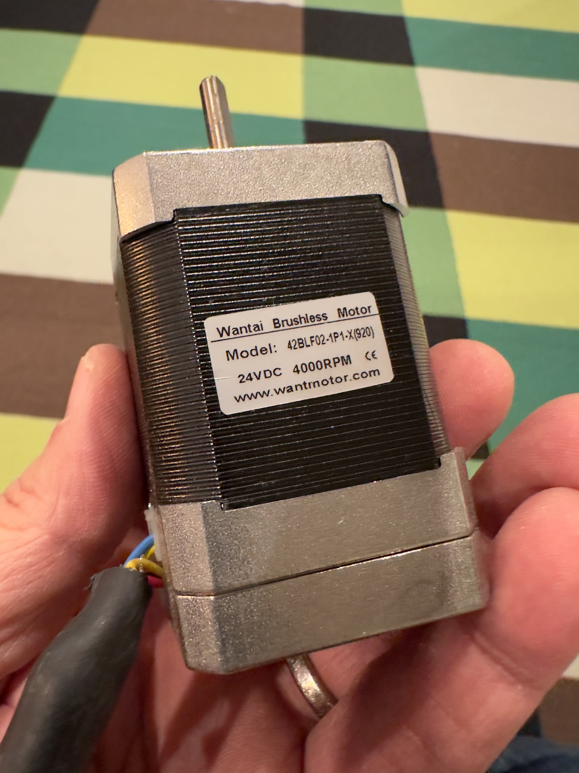
Thank you for the tip on searching for Bitrunner pinout. Would have not known to search for that. The Shapeoko has never been on my radar. I own the original Nomad not the Pro and my spindle has this motor.
Agree on using a RPi. Tried that already and found it slow. Not sure why. Will explore more. Still not addressing the stepper motor drivers. Would like to try 2209s. If I remember correctly you had great success with those.
Hello Lucas. Apologies if I am being a bother. Just got my new controller board from China and I am trying to configure the motors correctly. Using 2209 drivers now. My Nomad883 has Nema17 0.9deg Motors I believe. The X and Y are belt driven by a pulley of unknown teeth count. The Z motor is lead screw driven.
I am trying to search the forum to find some information that would allow me to make the calculations to get to the right steps per mm I need. I don’t know the XY pulley teeth count or the Z lead screw specs.
The current GRBL config options are XY steps_per_mm: 88.889 and Z steps_per_mm: 200.000.
Assuming that the old, original drivers were using 1/8 step?. Currently my drivers are set to 1/16 but able to set to 1/64.
I know enough to understand the way things work but not enough to read information and process it properly. It quickly becomes overwhelming. Any info you might already have from your past tinkering that might help me?.