I am unclear if this is an issue with my CAM work, Fusion, the Carbide post processor, or Carbide Motion so coming here for guidance as this is not the first time I have encountered.
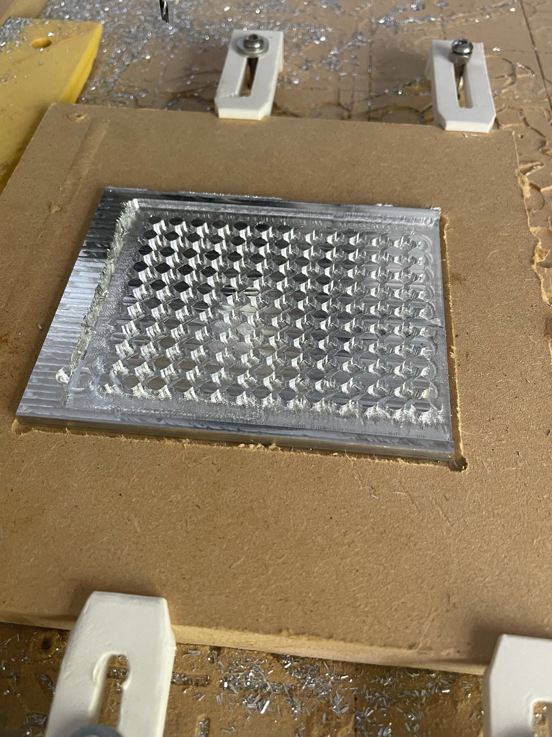
So I am cutting a Lego plate out of piece of aluminum for the sake of getting some more aluminum practice.
toolpath 1: surfacing with the 201 bit to model top
toolpath 2: 3d adaptive (with far more helical entries than I would have liked) to bulk clear as much as possible inside the part boundry.
toolpath 3: a 3d contour for finishing the studs and removing remnants left behind by the adaptive
toolpath 4: a 2d contour to remove the part from the stock.
(1) and (2) finished without a hitch. When starting (3) I realized I had not constrained the bit to being within the part body and the slotting contour of the entire part started. My speeds and feeds were too aggressive for this and I halted the job.
I then modify the setting for (3) such that the tool is constrained to boundary of the part (silhouette, tool inside boundary)…toolpaths and simulation look good.
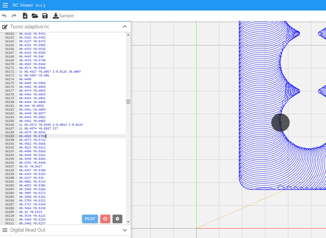
I go to run the updated (3) instead of moving directly above the bottom left stud the bit moves about 3mm left and starts cutting what would be the contour path around the stud…About where my black circle is.
Any idea what is going on here? Zero point is in the right spot but it just seems to be travelling ~3mm less to the right than it should before starting ramp.
Did you double-check your zero before re-running that updated toolpath ? You may just have lost steps during the previous interrupted run, messing with the X0 reference
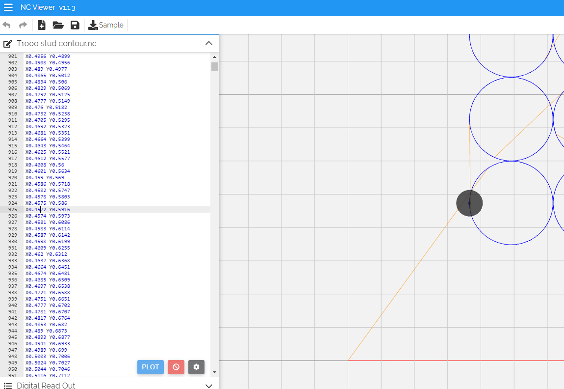
If this is not it, the first thing would be to visualize the updated G-code file itself to determine in the shift is present in the Gcode.
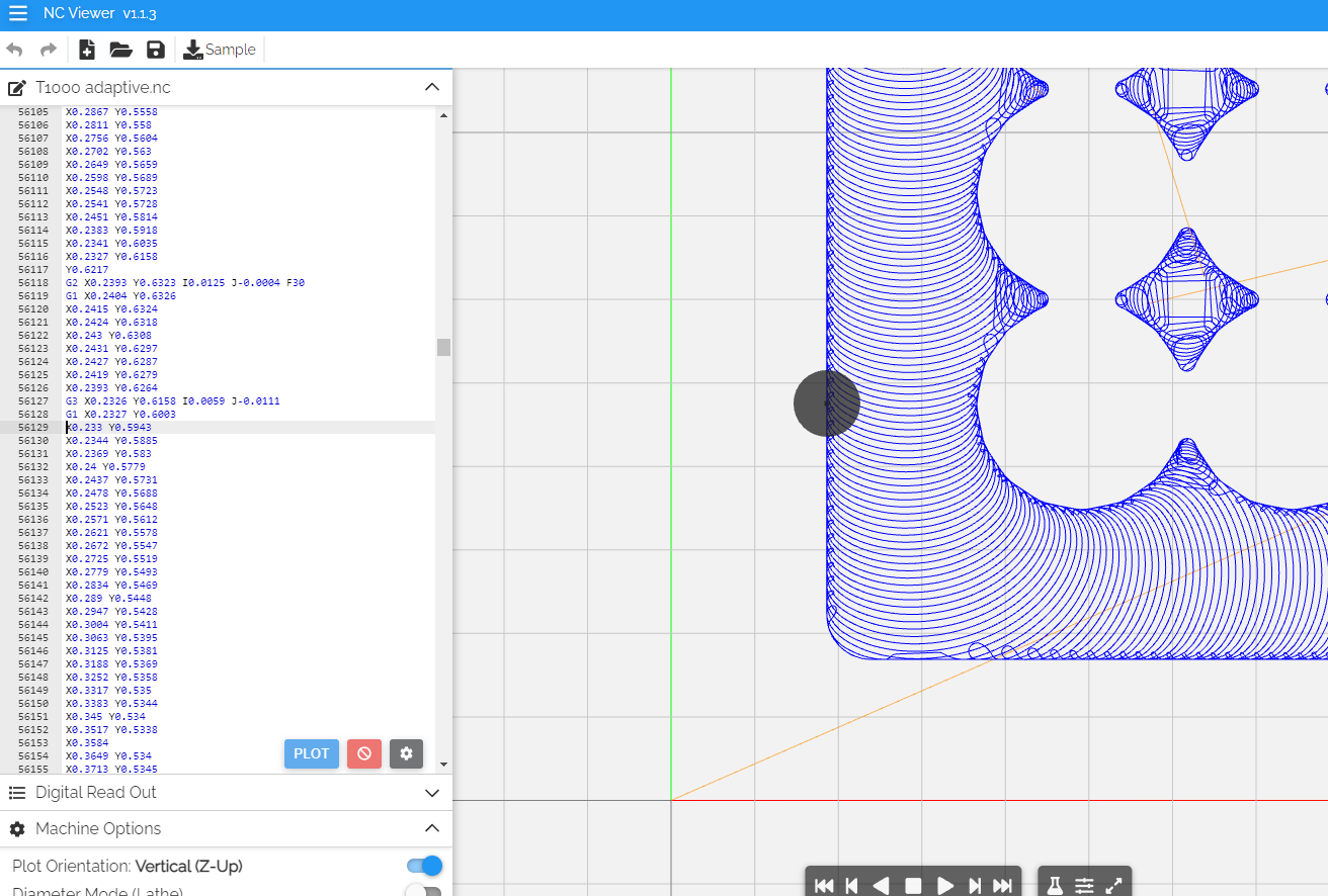
Yes. ncviewer.com has a very cool feature that you can click on any point of the toolpath and it will bring the focus to the associated g-code line, where you can check the X/Y values at the point.
That said, re-reading your original post this could just be something in the Fusion360 project itself. Can you share it for a quick look ?
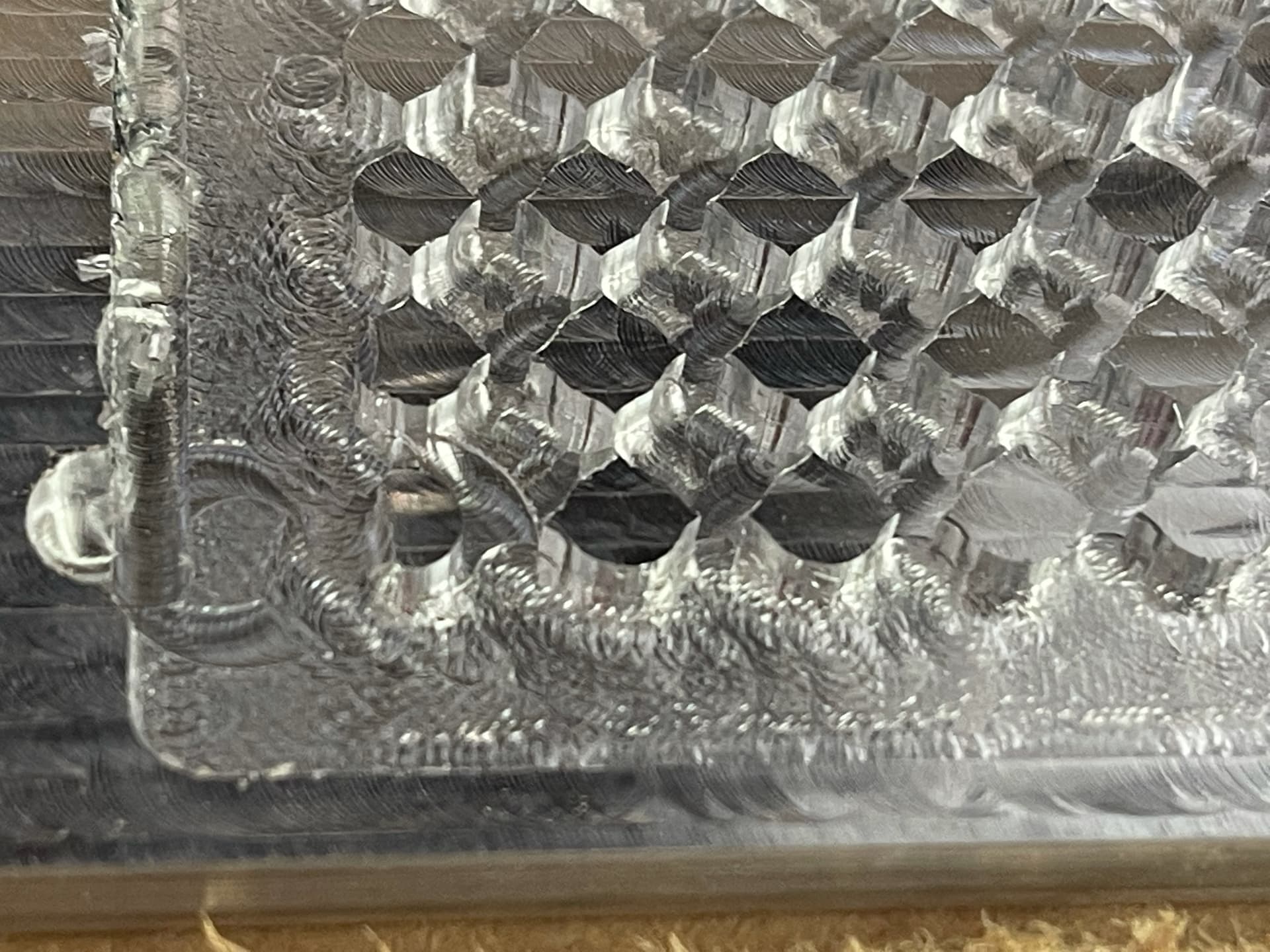
That. Imagine the cut your just animated being 3mm to the left with the rightmost of the contour cut going about 1mm into the stud. You can see the sheer here.
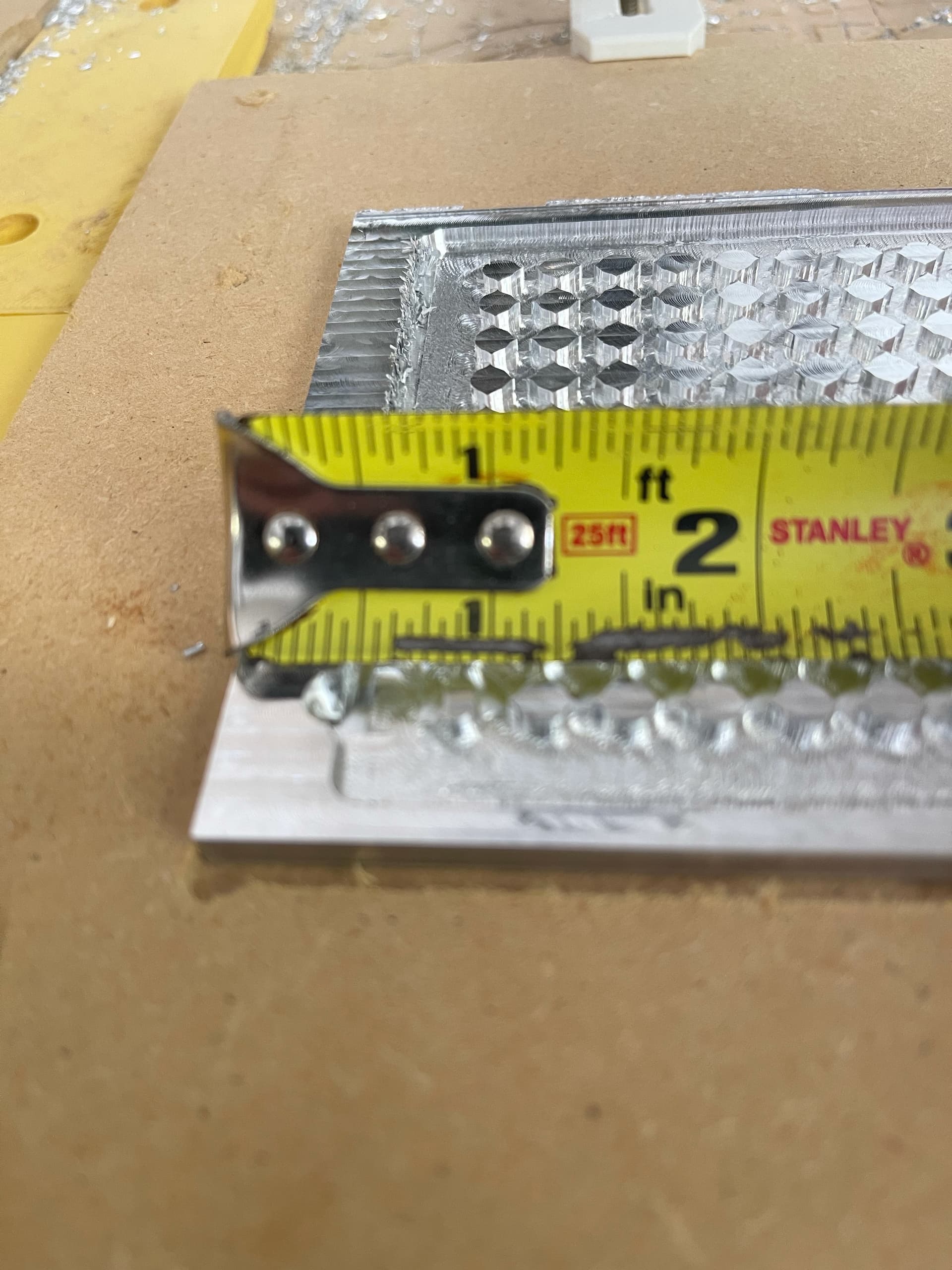
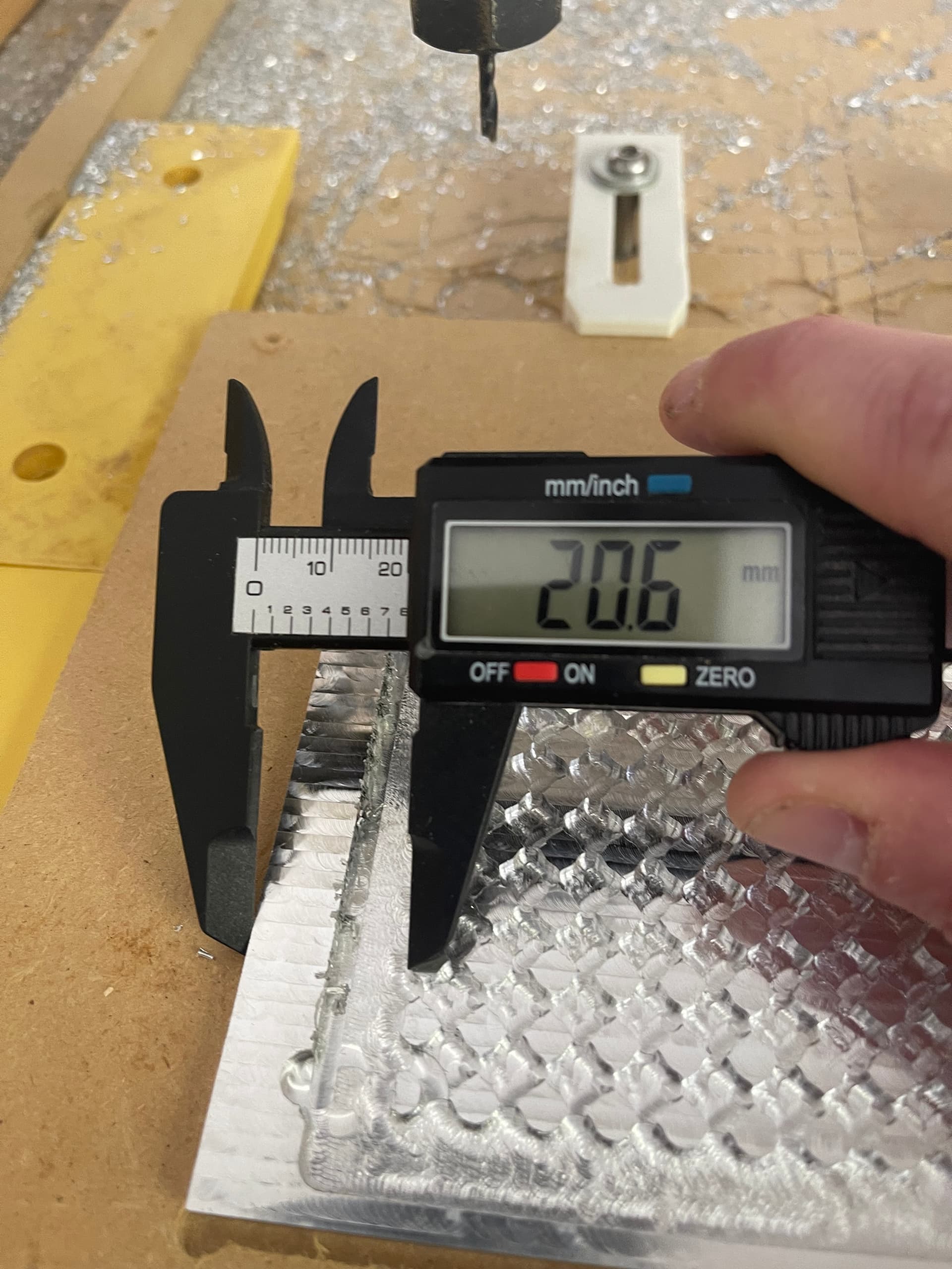
So I just measured with my calipers the distance from the left edge of the stock and the right edge of the rough cut stud…
.95"…adding half the bit with to get tool center…1.0125" is where the bit should be on the rightmost side of the stud. Both Fusion simulation and ncviewer show that point being .771" or .2415" to the left.
which does not seem to match the picture you posted ?
In other words, did you maybe modify the stock setup when modifying that toolpath after the interruption? modifying the model offset within the stock could have resulted in this.
EDIT: and the way to know would be to check the first toolpath’s gcode, can you upload that ? The one you ran initially on the machine
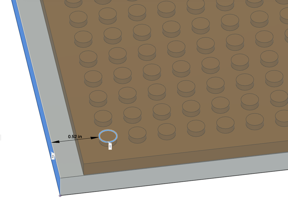
EDIT2: the gcode file of the PROBLEM toolpath seems ok, with 0.4572+0.0625" = 0.52" between the stock edge and stud left edge:
I had the stock and the body models as components with a joint connected the center of the bottom facing centers…not much chance for the spatial relationship to change. Unfortunately the original gcode is gone…let me see if I can recover by jumping to a previous save of things in fusion…since it does to version control.
My temporary conclusion is that the problem actually happened during the FIRST cut, when you ran the adaptive toolpath. There must have been a problem in the zero then, resulting in the adaptive run being cut shifted to the right. And then when the second (updated) toolpath was executed, it went…to the right place. I guess if you measure the distance from the left edge of the stock to the left edge of that circular dent, you’ll find 0.52" ?
That’s the correct way to do it, probing Z only to only account for the new tool length/stickout.
X0 (and Y0) should not have been impacted by rezeroing Z only.
The big question is, was X0 still correct just before you zero’ed the height only. It may have been left shifted from something before that. Did you visually check that X0 was still correct at that moment ?
The other thing I could think of, is that when you placed the bitzero on top of the stock to zero Z only, somewhere on the lower left corner of the faced stock, you may have unintentionally reset X0 ? I don’t see quite how you would have done that unintentionally though…
Thanks for all your help…and lesson learned: always rapid back to zero and eyeball for correctness before starting a toolpath…also I should break out that bitsetter I have to allow less room for human error.