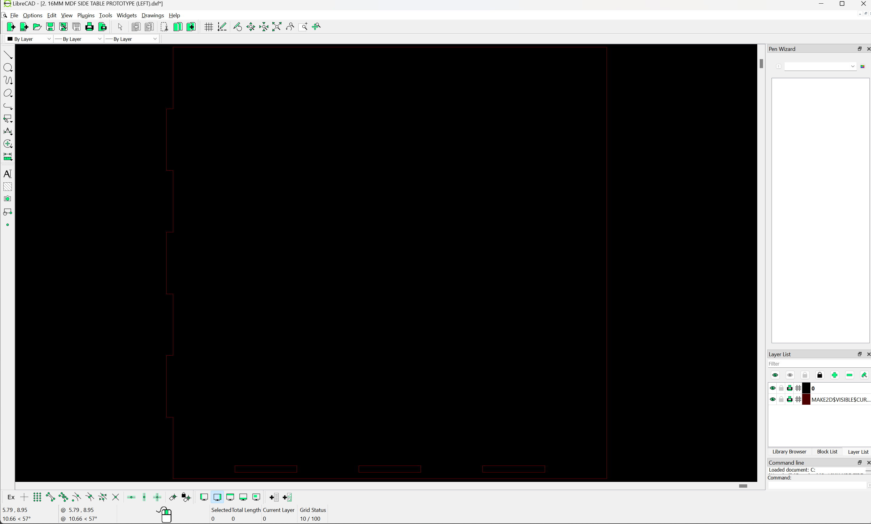
When I export my 2D drawing from Rhino 8 to Carbide Create as a DFX it imports at a tiny scale to the point where you cannot see the drawing. When I export from Rhino as an SVG file the measurements also aren’t accurate as per the original file in Rhino 8.
Does anyone have a workflow from Drawing in Rhino 8 to Milling in the Shapeoko 5 Pro?
What file type and settings should I use when exporting my drawing from Rhino?
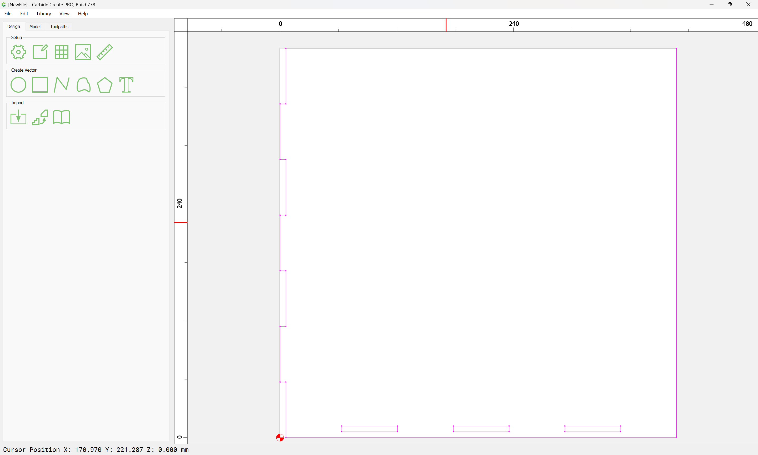
If you measure something when it first comes in to CC, and compare that to the known measurement in Rhino, is the difference 1:25.4 ? If so, you are saving the .dxf in inches, and importing it in metric (mm). Can you save the file from Rhino in metric?
OK, the .dxf looks like it’s already in metric. But the design comes in a long way from the origin so it messes up the scale/zoom. I don’t know Rhino, but you should be able to save it with the origin in the lower left corner of the design some how.
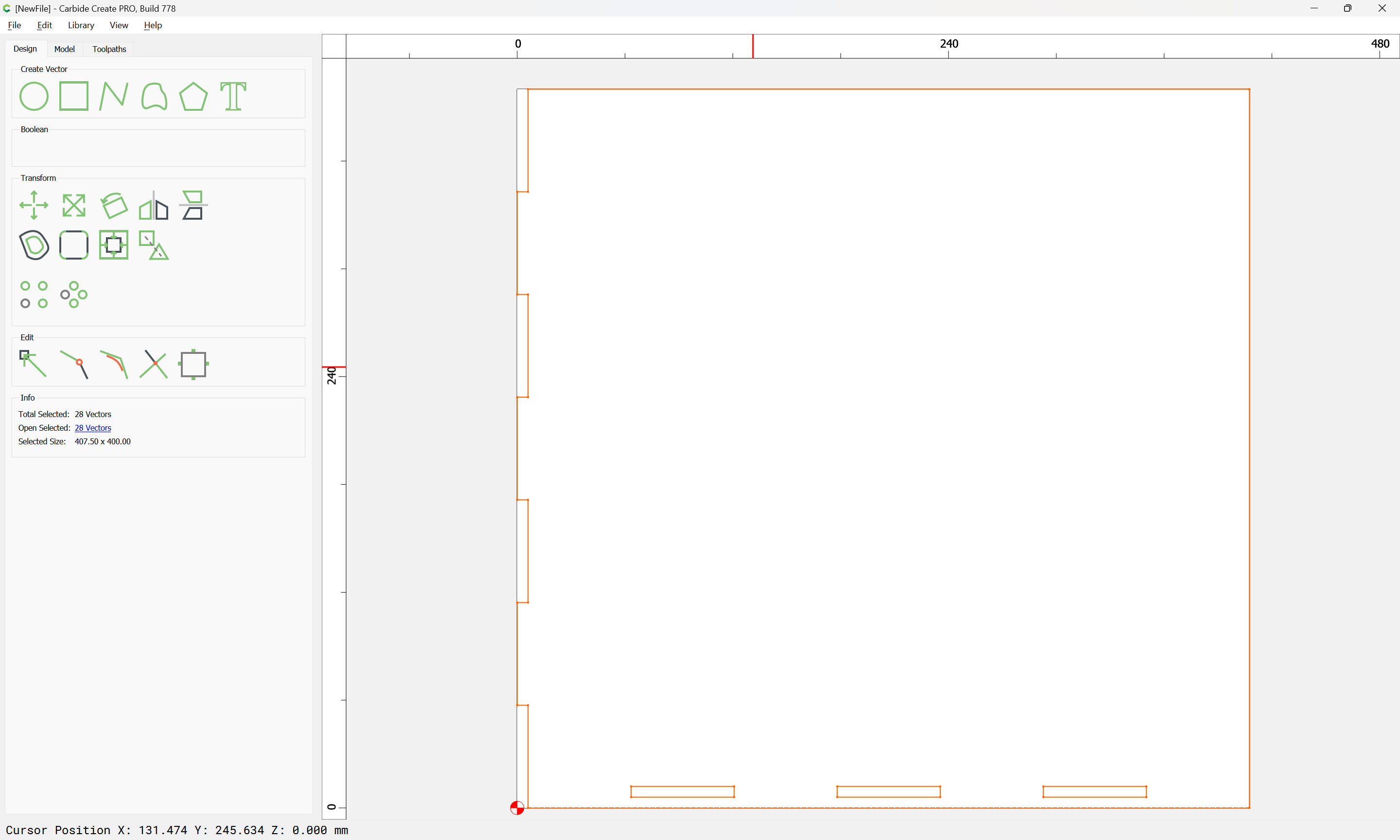
A little tip I use when importing SVG into CC – use a defined bounding box. That way when CC brings the art into the file slightly off scale all you have to do is select and group all the vectors from the SVG (l usually import onto its own layer for ease of selection) including the bounding box. Now the art vectors will be associated to the bounding box size and all you have to do is size the group to the known bounding box original dimension.
I will add that i have had better luck using SVG in CC than DXF.
That seems redundant. When you import a .dxf, .svg, trace an image or add a .svg from the library, it comes in at it’s native size & position. You don’t have the option to select a shape to import it to like you do with 3D imports.
Selecting the object, then Scale shows you the current ‘bounding box’ size. You can just change the dimension you want, either width, height or both.
Now a “Bounding Box” feature would be very useful. Select any number of vectors & create a bounding rectangle. This could then be used to position the curves using a corner, center or midpoint on the bounding box.
In my experience, adding the bounding box often assists in resolving slight scaling issues caused by rounding errors (just only look at one or the other dimension — don’t get caught up trying to make both X and Y match).
I use Adobe illustrator for all my vector graphics. When I export an SVG from AI then import into CC document, the SVG comes in at 75% scale. That percentage is not consistent Ive had some import at 68%, 79.8%, and possibly a few others but I don’t know because the easy fix was to use a bounding box. And as WillAdams added, it does address slight scaling issues caused by rounding. I am not sure why I am getting all the wierd scaling percentages but the solution I came up with was simple enought that I don’t really care why they come in that way.
If you instead export from Adobe Illustrator, and uncheck the “Responsive” check box when making an SVG to import into Carbide Create, the dimensions should then be correct (unless Adobe has changed that)
@WillAdams Thank you so much for the tip! Using Adobe for primarily print graphics I rarely have to deal with svg files and just never bothered to investigate those obscure toggle settings in the output dialogues. This wins the Tip Of The Day award IMHO!