I’m attempting to learn Fusion 360, so I’m sure this is a newbie question.
I’m attempting to create a flip-jig program that requires the stock to be placed @ 45° relative to the Shapeoko.
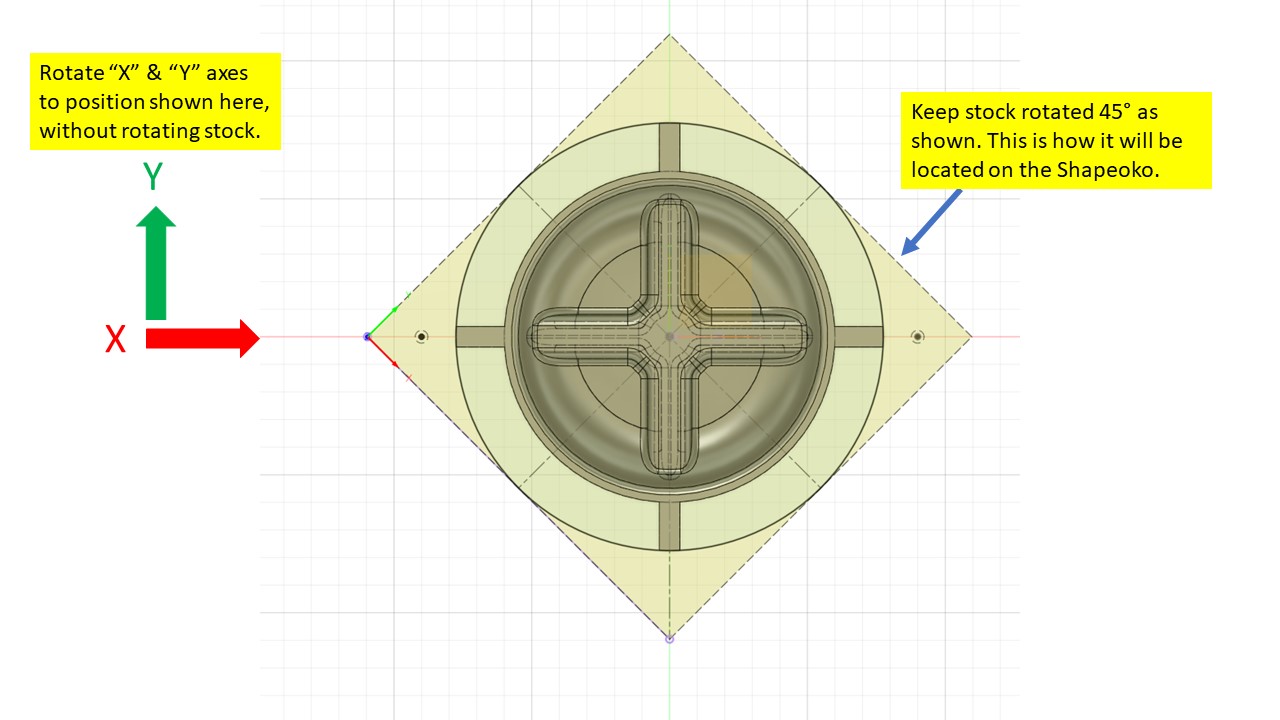
I created a sketch in the part to define the stock. This stock sketch is rotated 45° (to match how it would be placed on the Shapeoko). This is how I was planning on placing the stock on the machine. This allows me to place 6mm holes at locations that align with holes in my threaded wasteboard, while maximizing work machinable area.
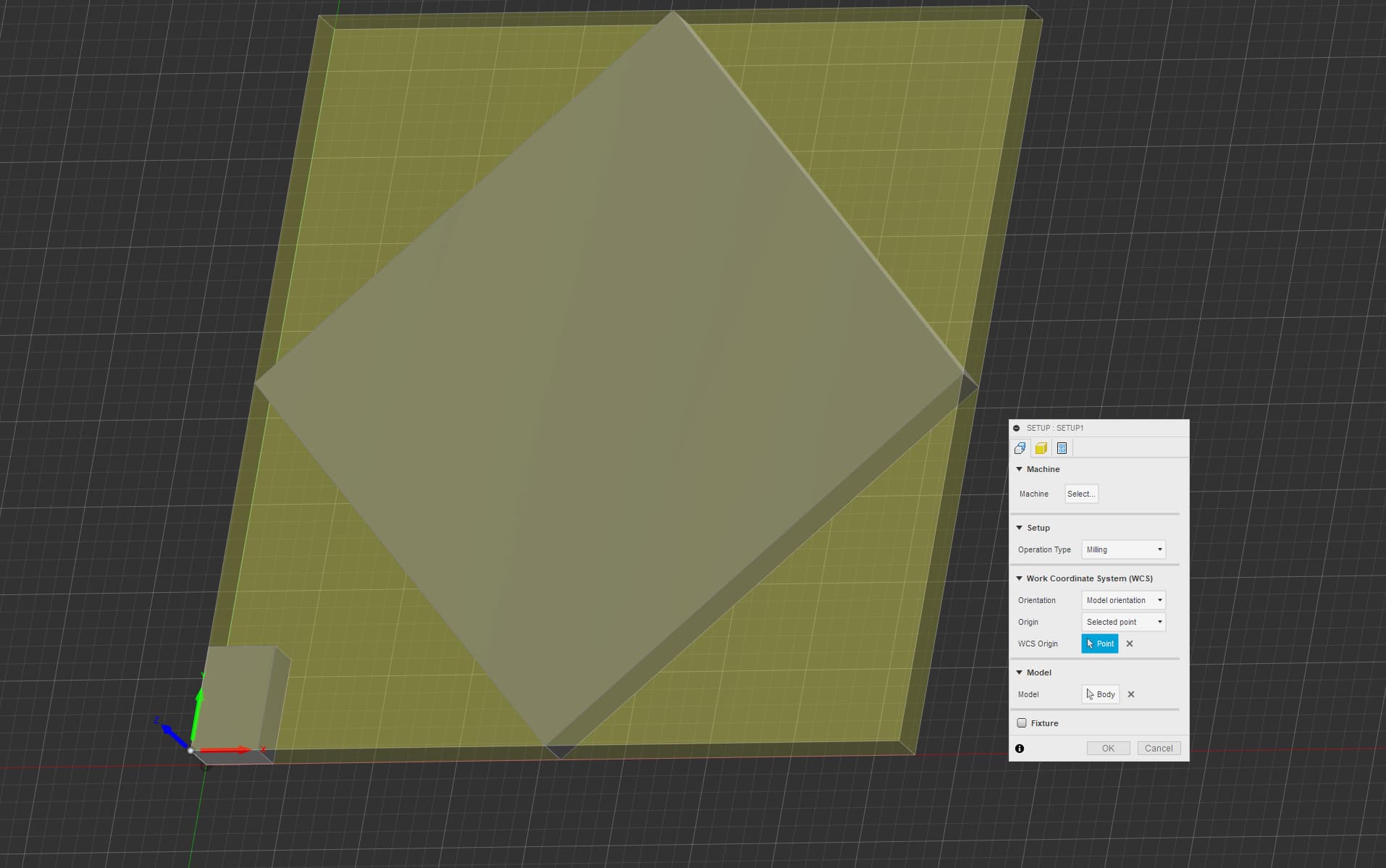
The problem is that I cannot figure out how to rotate the coordinate system without rotating the stock.
In the attached image, the stock is rotated correctly, but the X & Y axis are not. I’m assuming that the X axis needs to be horizontal and the Y axis needs to be vertical to match the orientation of the machine.
Not sure if this will help,
I use a 123 block to probe from and to set my origin in setup tab. You could set it straight on the table and turn the stock any way you want, the origin will be straight on the 123. Just make sure you have the block set properly in relation to your stock and don’t forget to remove it after probing.
I’m just beyond a Fusion newbie myself, but I’ll take a(nother)stab:
Editing my post after looking again.
It appears that you’re in the Design Workspace and all you’ve done is rotate the view via the cube thingie at the upper right. That doesn’t change anything except how you look at things on the screen.
What you need to do is rotate your part. As a newbie myself, what I would try is:
Create a new sketch in the XZ or YZ plane.
Draw a line vertically (in the Z-axis)
Finish that sketch
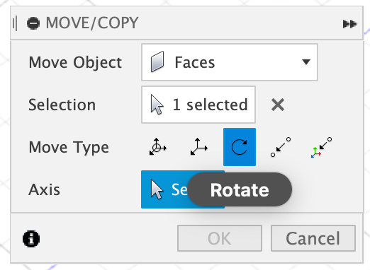
Select your part, then choose “Move/Copy” and get this dialog:
Note I’ve selected the rotate icon in the "Move Type Row. In this example, the thing to rotate is “Faces” but you want “Components”
For Axis, you have a selection tool active. Select the Z-axis line you drew in step #2.
Attached is a copy of my Fusion file. I clearly don’t know what I’m doing so any additional advice would be greatly appreciated. I have the part drawn and oriented as it would sit on the Shapeoko. However, it is my understanding that the X & Y axis on the CAM setup needs to be horizontal and vertical to coincide with the Shapeoko. I can’t figure out how to rotate the X & Y cam axes without rotating the stock in CAM.
On a separate note: do you know why my final Parallel toolpath cuts into the wasteboard?
I think I may have tried that before.
I think that the only problem with that solution is that it rotates the stock.
If the shaded yellow cube represents the stock then I’m guessing that the 6mm holes outside that area would not be able to be machined.
I think I need to rotate the X & Y axes without rotating the stock.
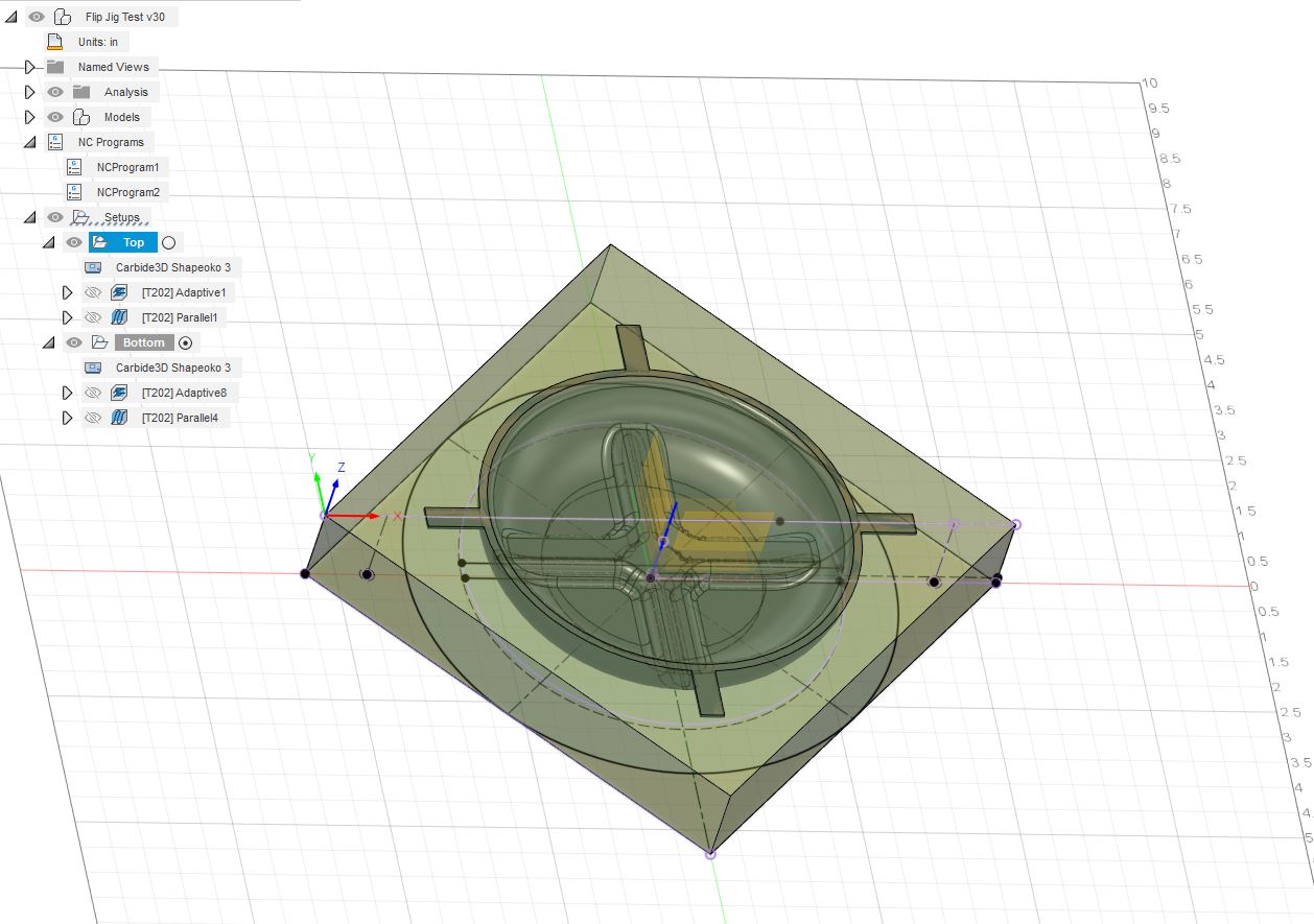
I did view run the simulation from your v30 file. I may be missing something, so please excuse me if that is the case, since I am new to Fusion.
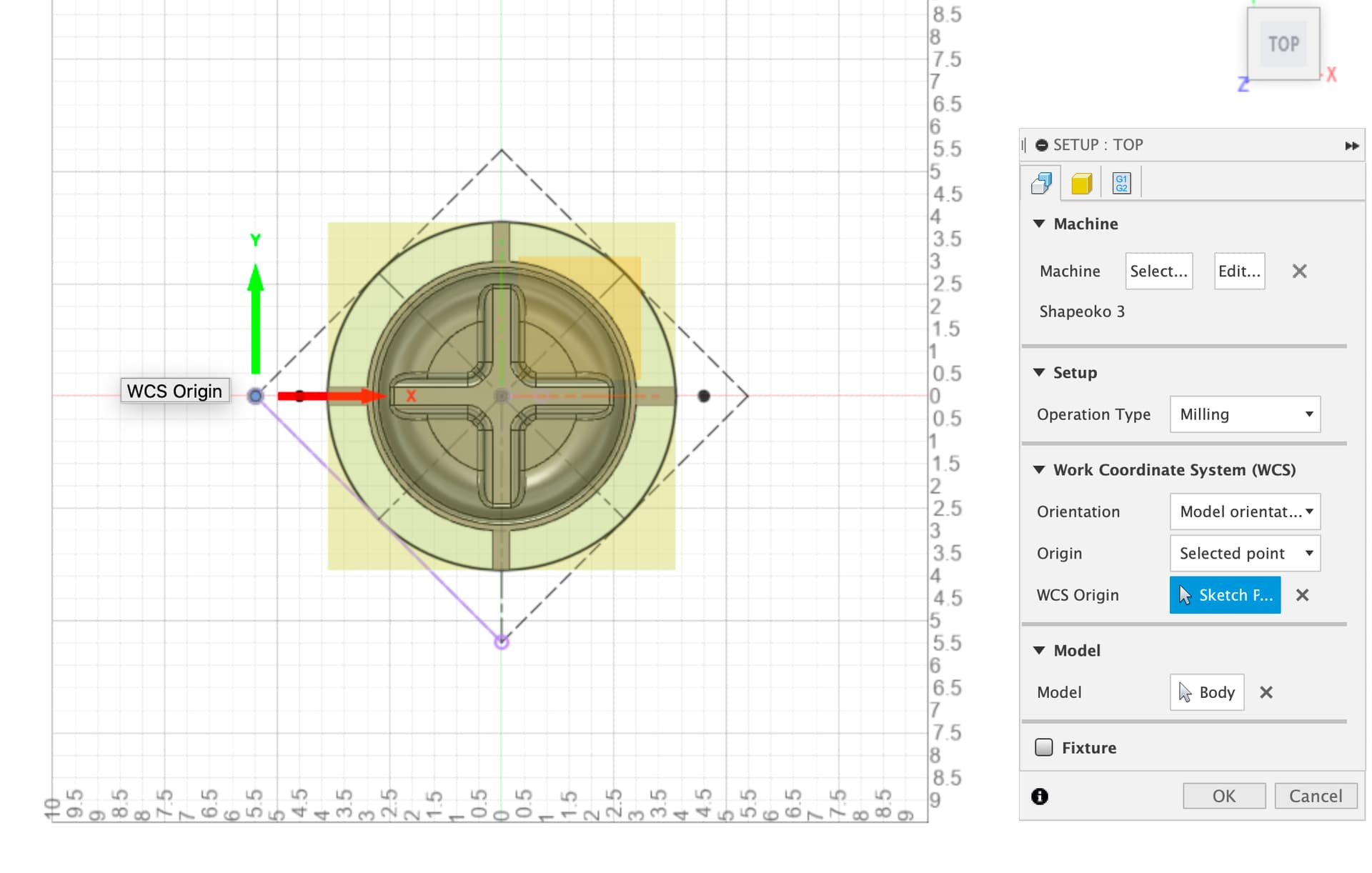
Your simulation shows the stock parallel and perpendicular to the X and Y axes. The attached image is a screenshot from your v30 file. Does the green shaded area represents the stock in your simulation? If so, it should be rotated as shown in my previous images, correct? If the green shaded area in the image represents the stock, then the holes in the corner would be inaccessible, correct?
It doesn’t look to me (Fusion newbie) that you created a body to represent the stock from which you’re milling. I think the shaded area is something auto-generated. Can you try going back to Design, create a body representing the stock and then referencing that in the Manufacture Setup?
I machined the top surface and it went perfectly.
I flipped the part over and ran the second series of operations and it went horribly wrong.
I am going to post that as a separate question.