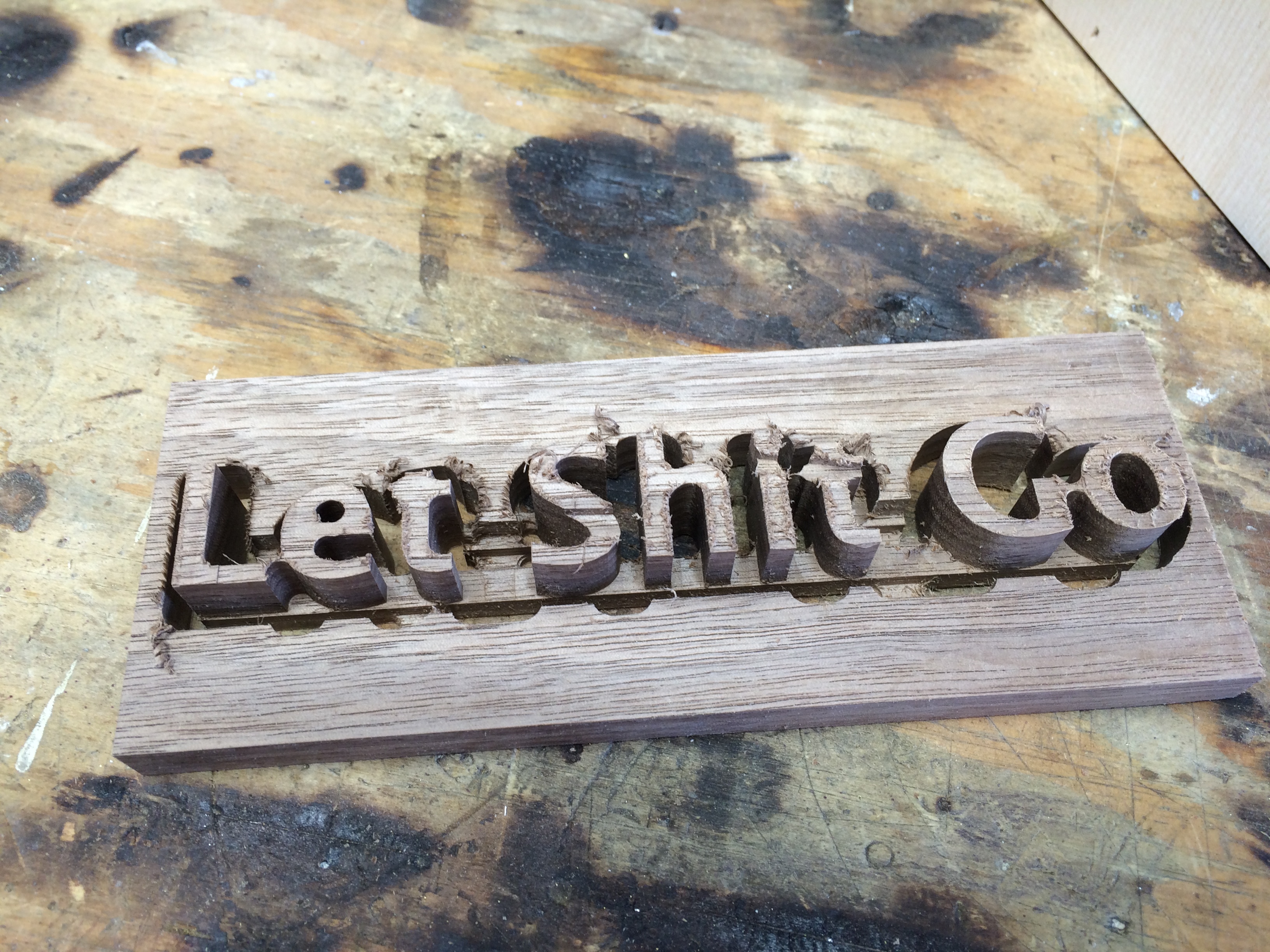
(apologies if you’re easily offended…but this is what I’m trying to make…)
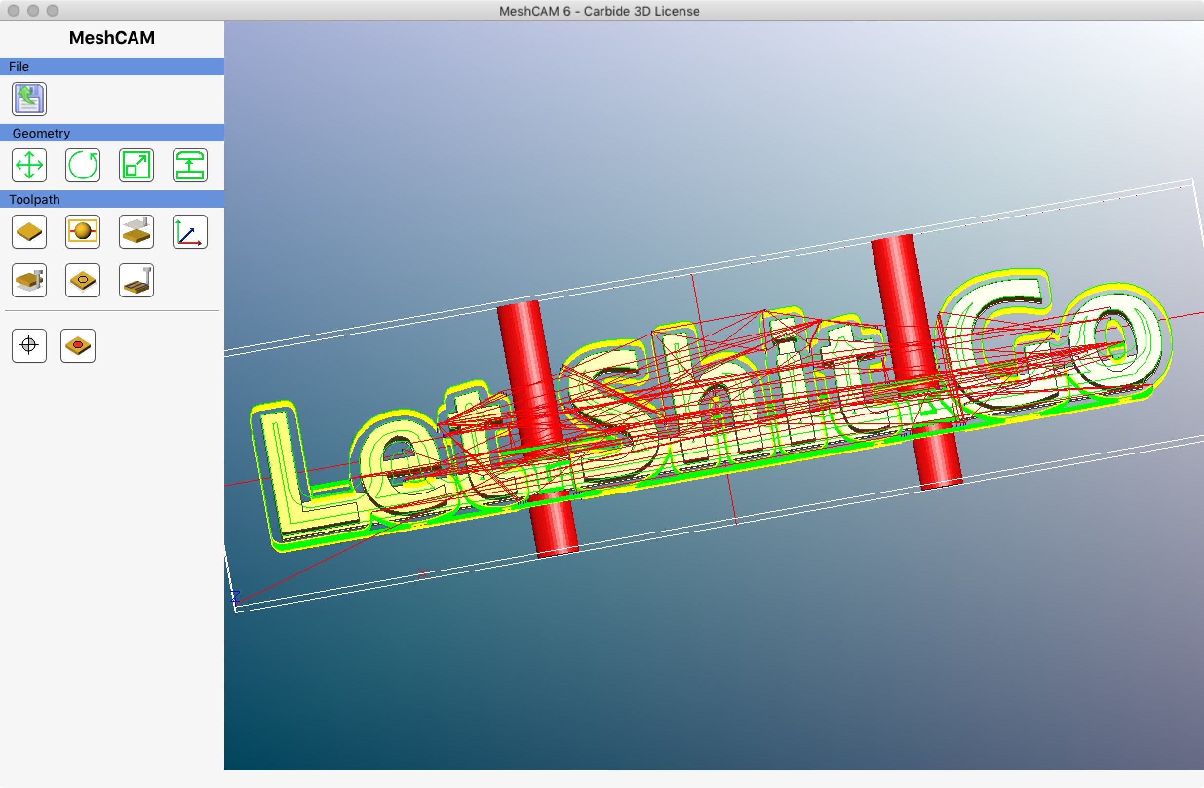
When I generate the toolpaths for this object, I get a roughing toolpath for half the geometry. the waterline covers the whole thing. I get -one- layer in the roughing path that happens at the very top of the material, then workdown across part of the geometry only.
The stock is about 6 inches x, 1.5 inches y, .8 inches Z.
If I select “whole geometry” it does indeed do the whole thing, but I had expected roughing around the full object when using “geometry only.” If that’s just how it works, that’s ok, but it seems wrong - I got one roughing path right at the top.
I don’t understand what I’m doing wrong here. Can someone that knows more about what they’re doing provide some guidance?
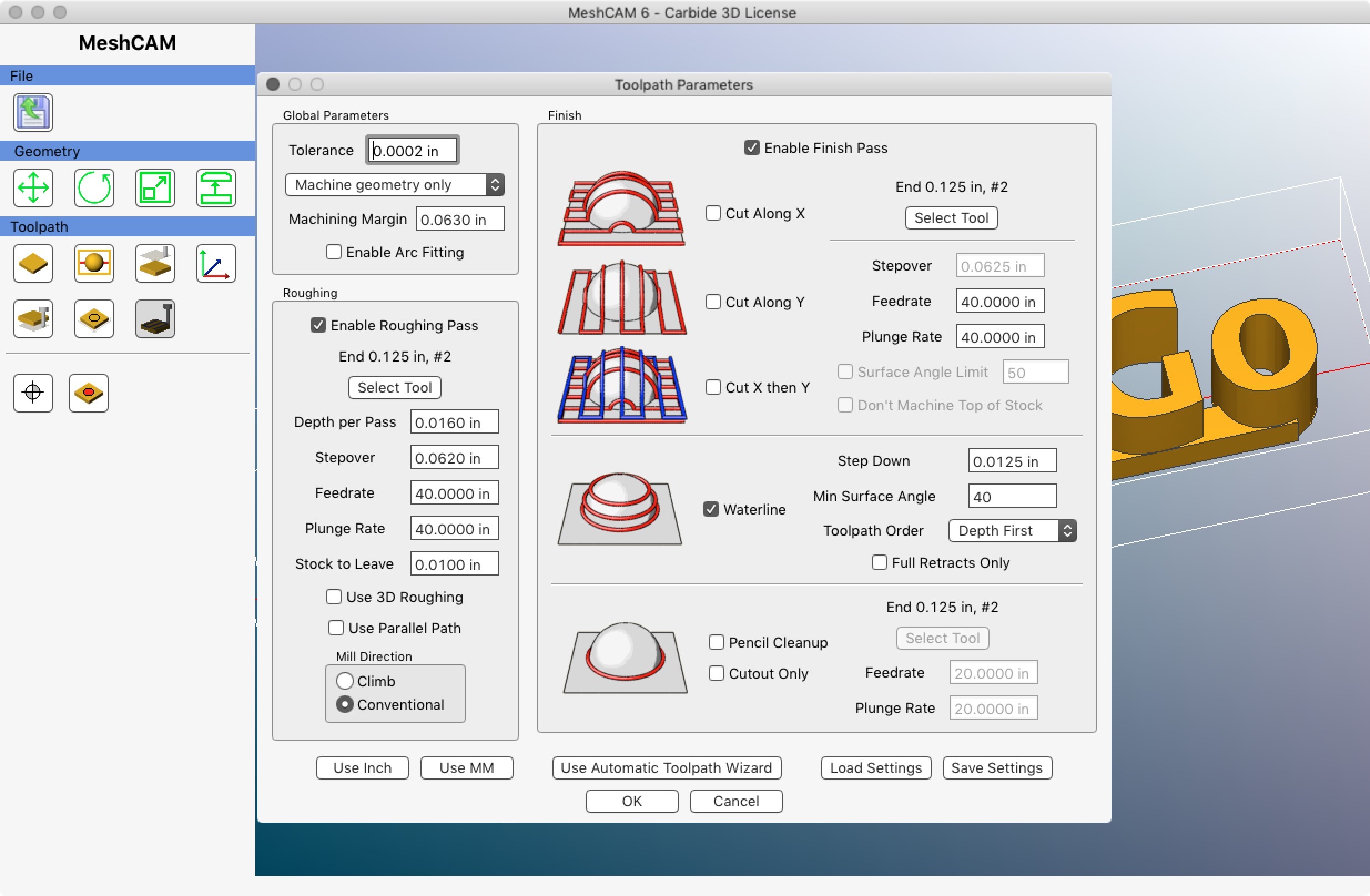
@mikep, increase your machining margin a little. Your cutter is .125" and the margin is exactly half that at .0625. That doesn’t allow for any calculation tolerance. Increase the margin to .07 or so. At a tolerance of .0002" you might get by with .065" margin.
Roughing toolpaths are not as smooth as finishing toolpaths becuase they are calculated with a different algorithm. That is why the finishing toolpaths are more complete on your example for the given machining margin.
.07 doesn’t do it, .08 and above seems to. What I don’t really understand is why I get even part of it then - what is different about the half that gets cut than the part that doesn’t that is triggering this sort of behavior? Is the vertical component of the bar across the back getting things into a different algorithm that what would be used for cutting all the way through? Or what specifically is different about the ascender on the “L” being different than an arbitrary standalone “L” where the standalone “L” the whole thing gets a path (at the same scale, tools, etc) but only part of it does in this case? There would seem to be plenty of room between the L and the “e” for that part of the path. Not questioning your answer, because that does get me exactly what I wanted, just trying to understand better.
@mikep, there is another factor I overlooked–Stock to Leave. For the roughing, the geometry is effectively .010" larger all around. That would factor into your needing .08" instead of .07" of machining margin. As to “why” it happens, I don’t have any insights into Rob’s algorithms so I can’t really say. I just observe MC’s behavior and try to work out a coherent picture of “what” happens.
Over on the MeshCAM forum, I’ve compared MC to a blind person with a cane. The workpiece is in front of them, the machining margin is a wall around the geometry with a certain gap, the cane is the cutter, and the tolerance is a thickness of masking tape wrapped around the cane. To feel their way around the geometry, the person needs to be able to swing the cane. Too small a machining margin and the cane jams so the person stops. A larger tolerance means a thicker layer of tape on the cane, which makes the situation worse. Probably it is an entirely different scenario, but my mental picture does fit the behavior… So maybe the person is left-handed so they can feel better around one side of the geometry…
I think I ran into the “doesn’t retract right” bug, across the S and the IT. While watching it, it did this on two layers, not retracting, then started retracting the full amount. Strangely appropriate for the content on the sign, I think I’ll leave it that way.
Roughed with a .25" mill, finished with a .125", then a little touchup (LE, IT, and GO) with a knife. Needs a little more finish work, but you get the idea.


 So maybe the person is left-handed so they can feel better around one side of the geometry…