You seem to be asking several questions. Perhaps semantics??
How to model a roundover? How to cut a roundover? How to simulate a roundover?
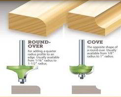
The edge in the picture appears to be a cove.

To model a 1/4" roundover on a 3/4" thick workpiece…
Offset the vector inward 1/4" twice.
Use the first offset to build a flat component 3/4" tall.
Use the Original vector and the 2nd offset to build a round component, 90°, scale height: 1/4", Base height: 1/2", And use the “Max” merge type.
To use a 1/4" roundover bit (without bearing) on the machine.
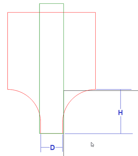
Measure the tip of the tool. Offset your vector outward 1/2 of this diameter.
I like to add just a few thousandths to make sure I’m not cutting with the sharp edge.
So if the tip measures 0.375, take half (0.1875) and add a couple thou (0.190) and offset your vector that far.
Create a contour path, no offset, 0.2475 Max depth (same 0.0025 gap).
Or in the image, “H” minus the couple thou.
To Simulate a roundover, Check out Will’s solution here… Using unsupported tooling in Carbide Create: Roundover / Cove / Radius bits
