You had your stock height set to 0.750. I don’t know where you got the 0.350 from??
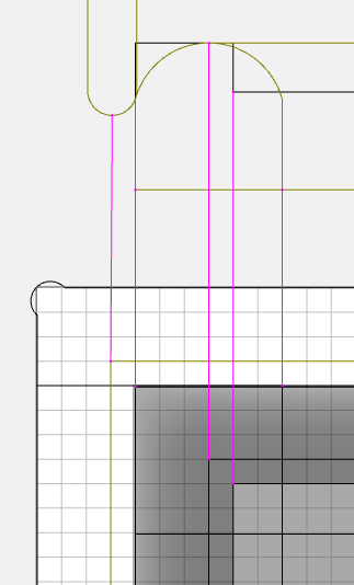
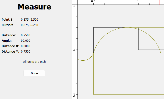
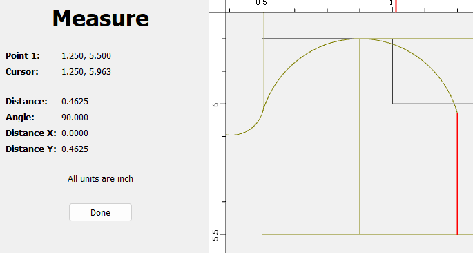
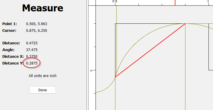
The boundaries are the vectors you choose when you do a 3D toolpath. The tool will stop, stepover, change direction ON the boundary. The center of the tool will cut to the boundary, so the edge of the tool will be past the boundary by the tool radius. So I laid out the tool in my side view so it was tangent to the radius, and then transferred the center of the tool down to the plan view & used that offset for my boundary.
I started from scratch and this is what I have from trying to follow the instructions above, I end up with the square lid and pocket but no rounded edge BoxLid-Instructions.c2d (60 KB)
I’ll be honest I am completely lost beyond the square lid being 6" x 4" and the pocket being .25 deep and 5" x 3" the whole tangent, corner, round and max, min etc. for it I am lost with all the numbers as I have tried different settings and different numbers mentioned above and I either get a protruding sphere , a hole, or nothing at all
I tried modifying the toolpaths, not sure if I did it correctly I am not getting the same times as you. Not sure if we have the same end mills.
I used the box lid you had uploaded and modified the tool paths trying to follow your instructions. I could not get the blue like you did in the first image for the tool path here. Box Lid5.c2d (160 KB)