How would I take a square top for a box and round the corners, I dont want them like a perfect roundover where its a 90 degree curve I want a more gradual curve from the bottom edge to the top and each corner to come to a point so that the corners of the top match the square corners of the box.
I tried previously to design this and failed. Any help would be appreciated. I am very inexperienced with my CNC and have only done a few pockets and cut outs with it.
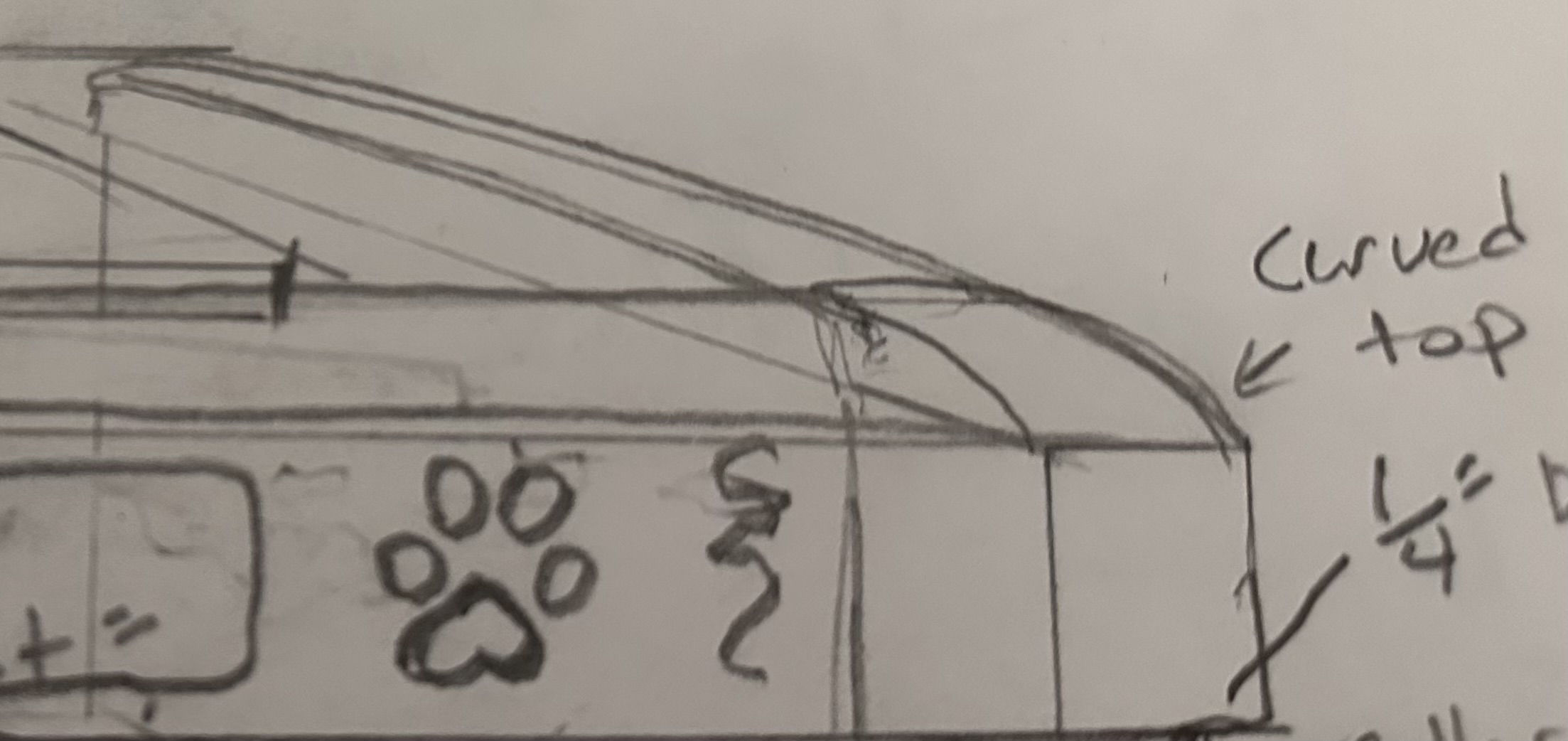
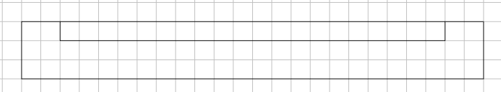
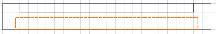
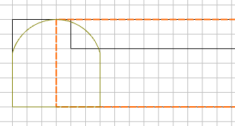
This is what i want the top to look like (see attached drawing)
The center of the lid would have a pocket in it as well for an inlay
Thank you in advance
Note: my previous question on this got auto closed as I had surgery and couldn’t get back to my post in time.
I have also attached the file. but not sure it is going to cut correctly Box Lid2.c2d (208 KB)
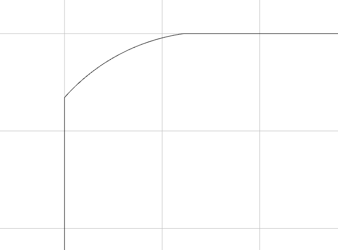
The very first thing you could do for us so we can help you better, is draw up a cross-section view of what you would like to accomplish, and post it on this thread.
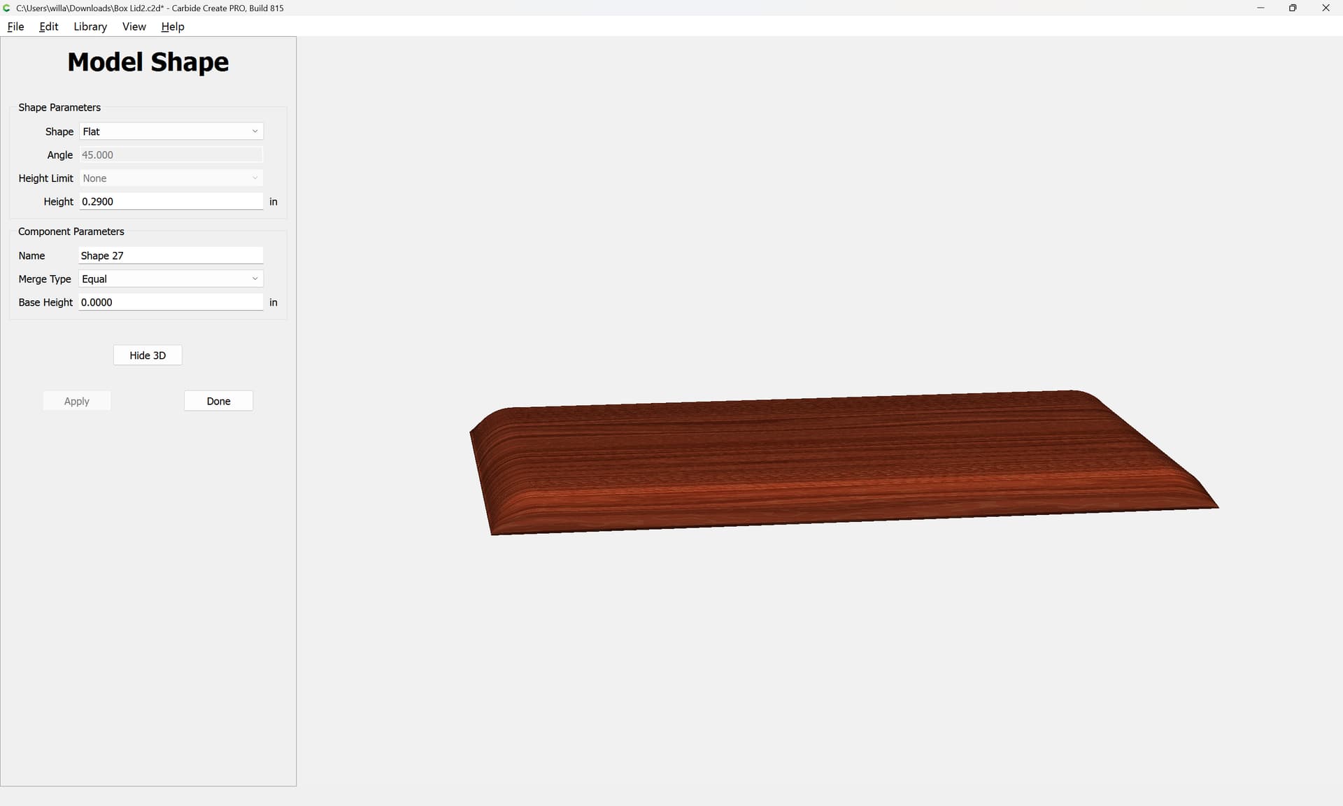
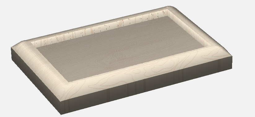
I’m not 100% sure what you are hoping to achieve but I think I can guess.
One thing I am learning is you don’t have to complete your entire project on the CNC machine, sometimes it’s easier to use other tools.
For example if you had a router table with a roundover bit, and you ran your box top in a straight line against the fence on all 4 sides I think that might get you the profile you want?
I have a hand router that I bought before I went into the hospital and honestly I should have gotten a table instead. But now its too late to return it as its been like 60 days now
Thank you so much. That looks exactly how I wanted it. i did want a pocket in the top for a 1/4" thick inlay. Where did I go wrong in my design and toolpaths ?
For what it’s worth, several companies sell a jig that turns a palm router into a router table. I think I I picked mine up from Lee Valley but there are probably other better options and less expensive options out there.
Obviously not as good as a dedicated router table with a full sized router, but I mostly use it for round overs and find it very useful.
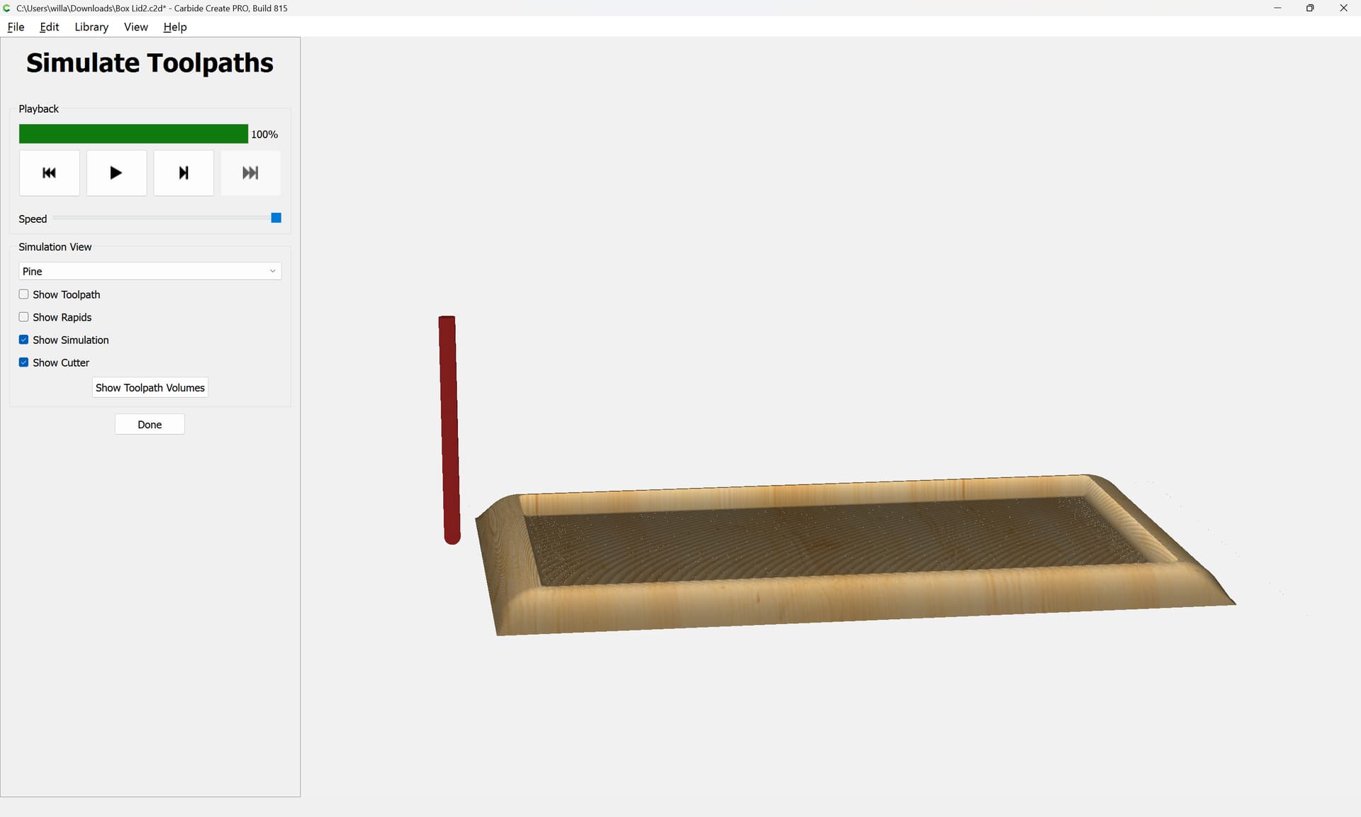
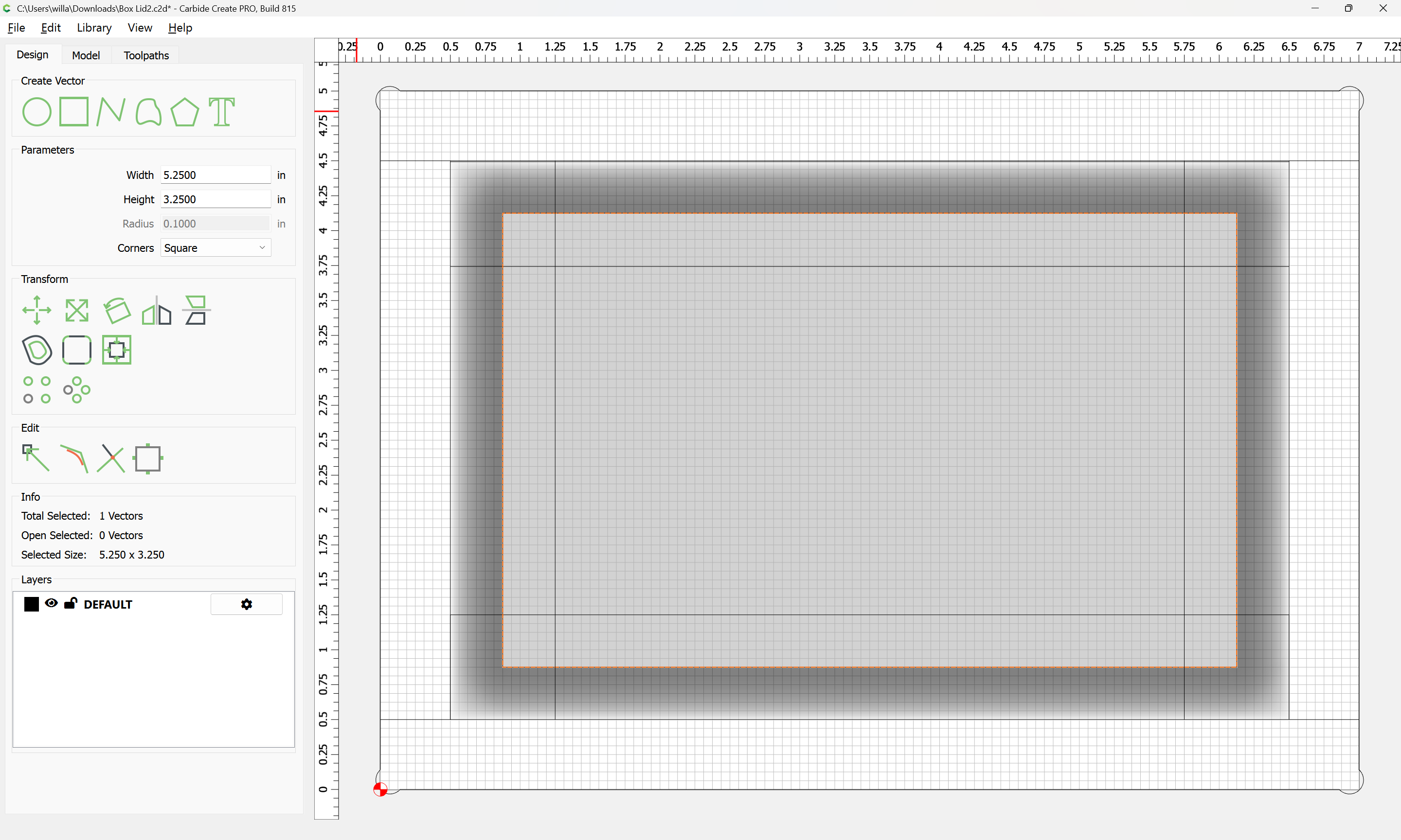
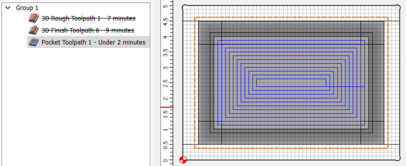
Hi Will, I Tried adding a 5" x 3" square and then pocketing it to a max depth of .27 but on the simulation it seems to be ignoring it. What did I do wrong ?
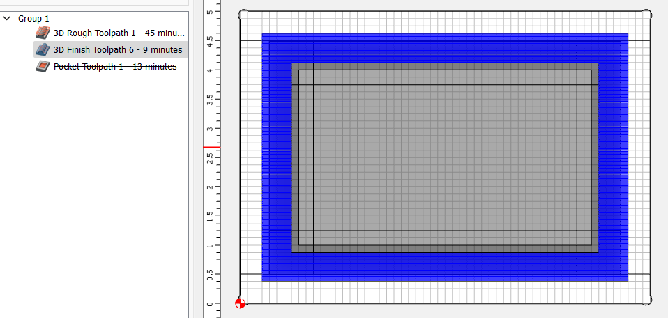
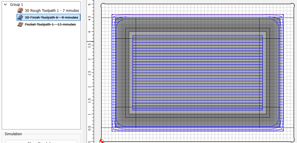
and this correct 71 minutes for the 1st pass tool path and 53 minutes for the second ? It seems like a lot longer then it should be
I took the plastic spacer off the base & screwed the base to a 1x12 with a hole in it.
Clamp that to my bench or table saw & instant router table. I added dowel holes & a 1x2 fence to use as guides.
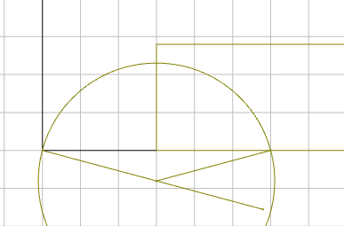
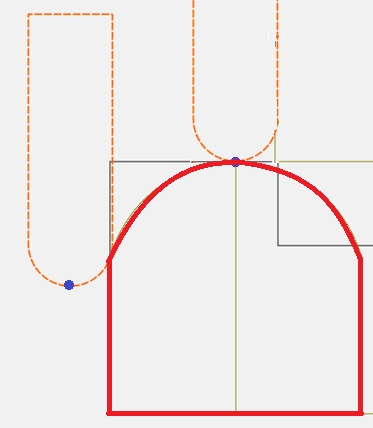
Next component(s) are the rounds, Round 75° 0.790 Limit Max on the 3/4" wide rectangle.
Since it’s 3/4 wide, and the angle is 75°, the height calculates out to about 0.288.
The Limit Height doesn’t do anything because the initial shape is less
If you think about it, the only 3D portion of the project is the rounds.
No need to cut the entire model using 3D.
Also, there are no tight corners in the 3D model, so the rule of thumb is “Use the largest ball mill you have that will get the detail you need.”
Let’s assume your largest ball mill is a 1/4"
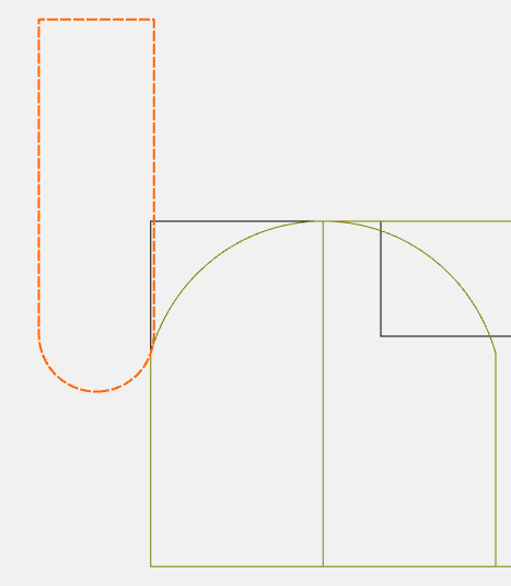
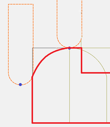
Make yourself an offset rectangle around the outside to allow the ball mill to be tangent to the steepest part of the round…
I appreciate your help and Im trying to follow along but the instructions lost me. Im not sure what you mean by flat .350 max on centerline of the round. when its a top down view and you show side views. I must be doing something wrong as I cannot get the rounded edge effect when I select to model a round it just works for that corner not the whole perimeter of the job.
Im also completely lost on how to setup the finishing paths
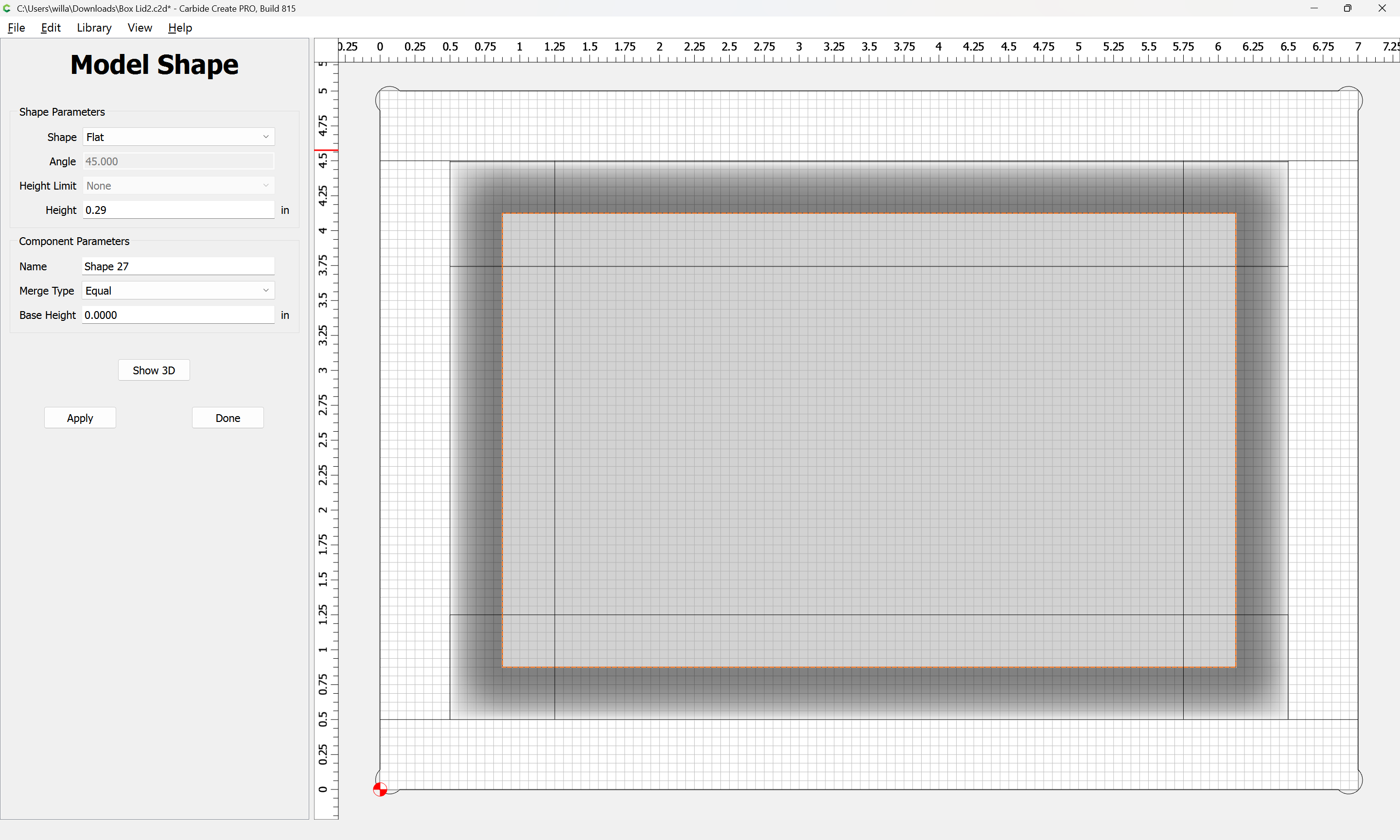
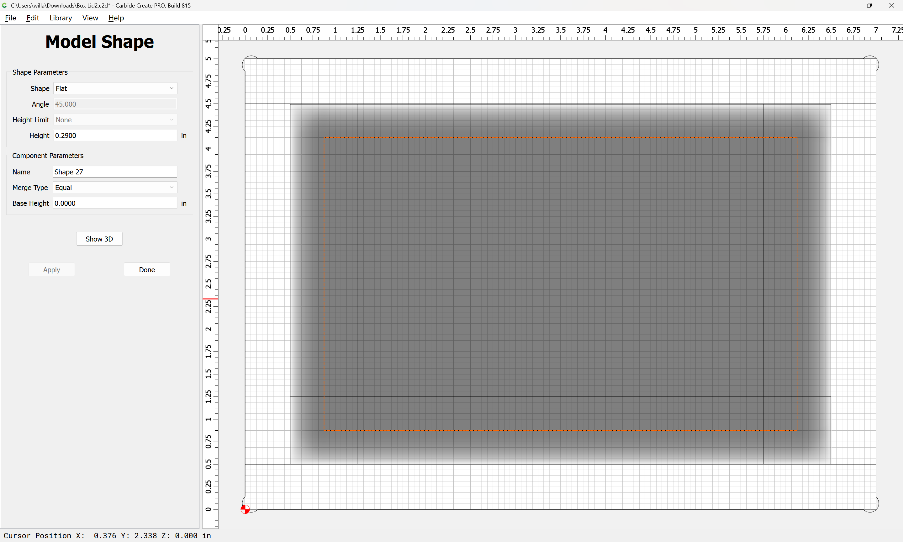
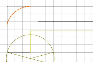
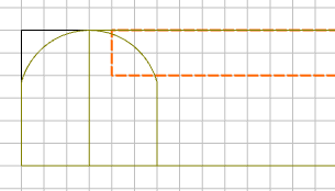
You made a flat component, 0.350 height, MAX merge type. 0.350 is below the 0.500 thickness in the pocket area (0.750 stock - 0.250 pocket). So the 0.350 component is redundant & buried beneath the desired final product.
I use the side views to make sense of the 3D construction and where the tool boundaries need to be.
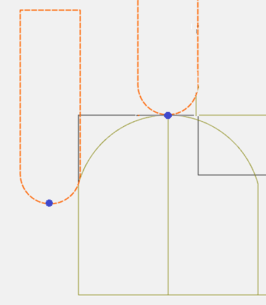
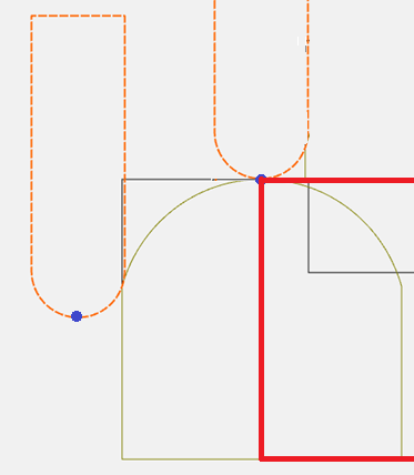
If you’re only cutting the 3D portion with 3D, the boundaries represent the center of the tool at the tangents of the rounded edge. So your boundaries need to be where the blue dots are.k
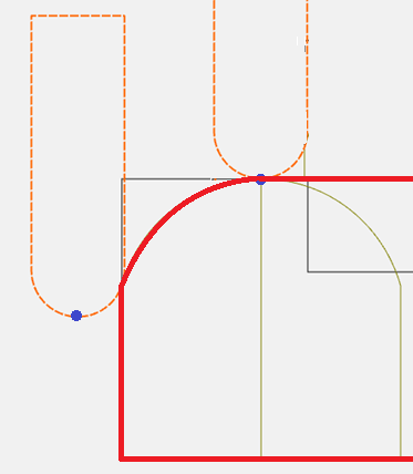
For the outside edge, since your radius starts at 75°, rather than 90°, it’s just a little less than the radius of the tool (0.125 for a 1/4" tool). I just use an offset of 0.125 and check the simulation to make sure it doesn’t fall off the edge & cut through the stock. If it does, reduce it to 0.120
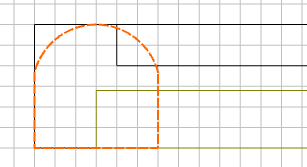
Or you can leave the pocket out if you are only cutting the radius with the 3D.
In fact, you can leave the initial 0.750 flat component out too, and just build the round component.