I programmed it in NX CAM. I got it as close as I could to the same process that CC uses. Same stepover, cut depth, speed & feed. I added 2 extra semi-finish passes at 0.010 & 0.005 with the V bit, and the most crucial difference is using climb-cutting for all finishing passes. One thing I didn’t do that CC V-Carve does is pocket out the corners with the V-bit where the end mill wouldn’t reach. I have some small chisels that would zip these out by hand pretty quick.
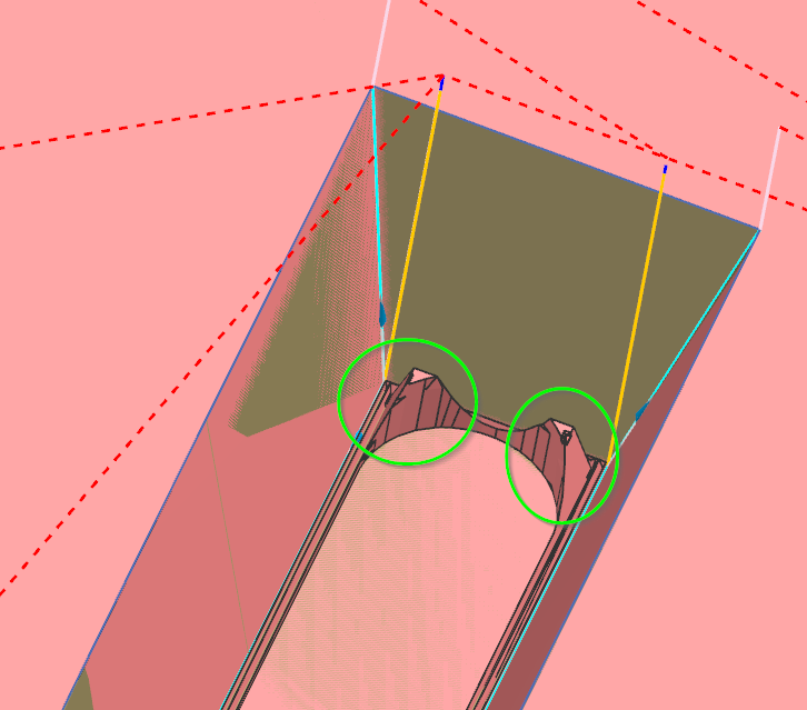
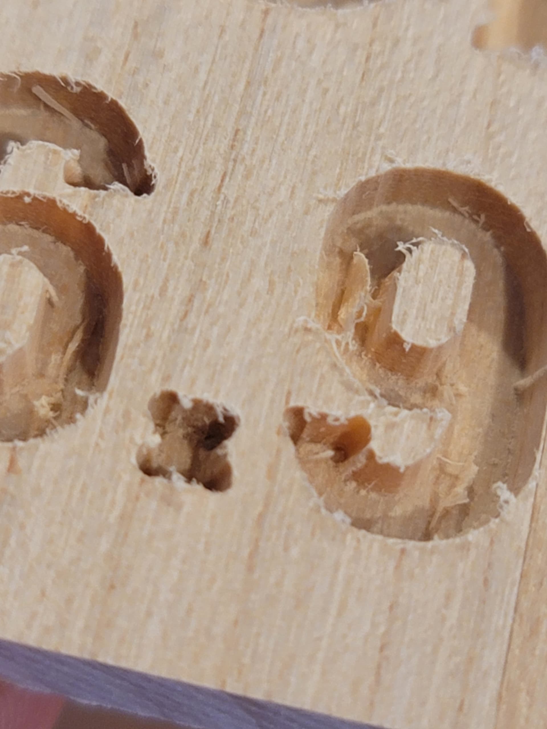
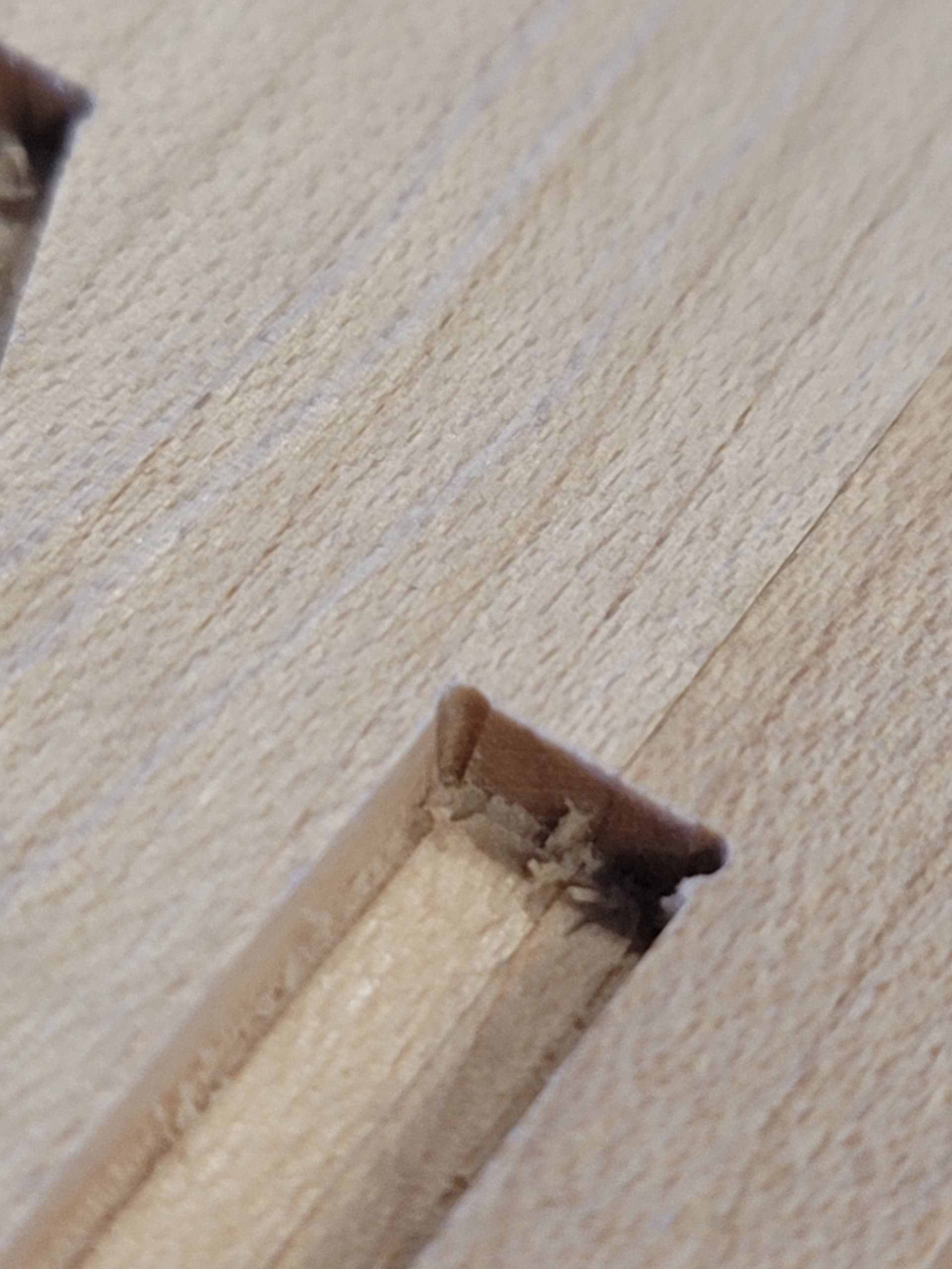
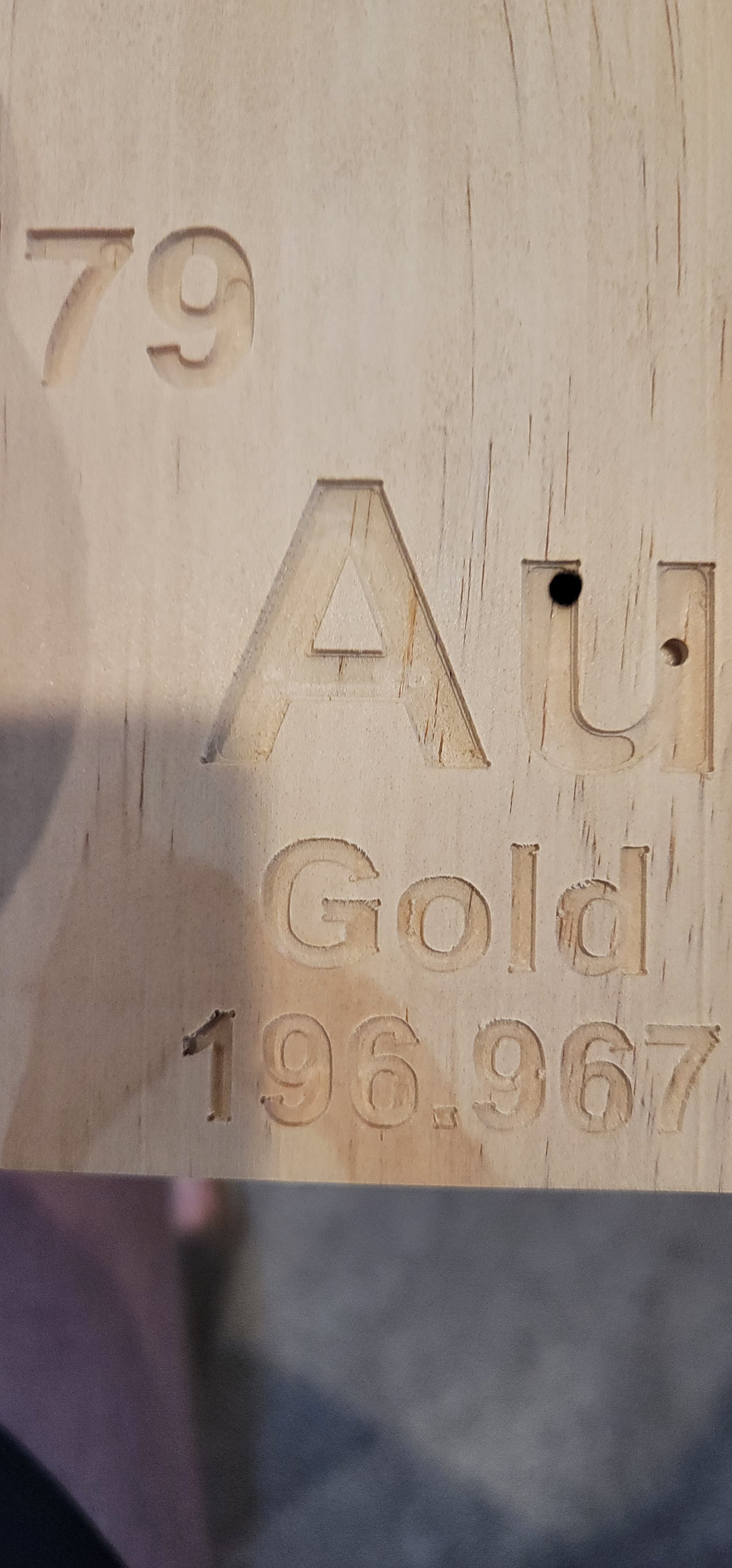
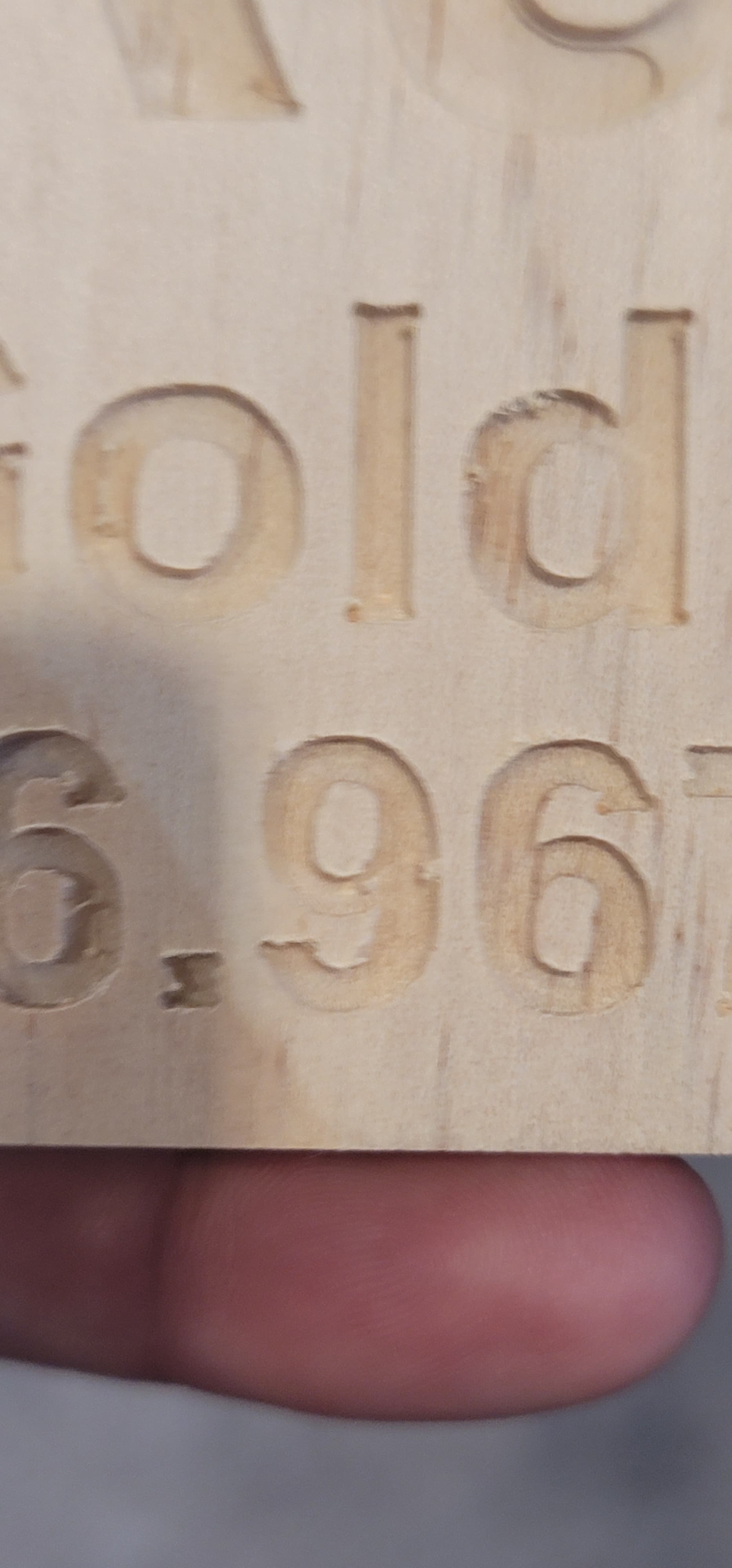
So i tried running the whole design I used a 15 degree bit and went .1 inches deep. The results are not stellar, its really rounding every corner. And while watching it looks like it plunges straight down into the corner, which the close up pictures seems show. Any thoughts? As is this is not usable.
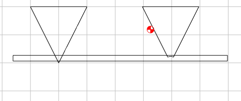
What does the tip of your vee bits look like? Some vee bits have a rounded tip and that fools the BitSetter to set the cutting depth lower than intended. CC only uses vee bits with a sharp chisel point. When the end is rounded and it comes down on the BitSetter CC expected the bit to be longer and therefore sets the bit lower than it was supposed to be. This has bitten quite a few people.
Below in the picture the left vee bit hits the Bitsetter and is set at the correct depth. The one on the right with a round nose will travel further down and will cause the BitSetter to be tricked and set the depth lower because of the difference between the sharp point and the round point. CC does not know about round end vee bits.
The picture is a little exaggerated but it illustrated the problem. If you have a magnifier glass look at the bits you are using. It could be one of C3D bits but if you ever dropped it the nose could be broken off.
Hey, i appreciate it, but i tried this. Im using an amana 45611-k 15 degree bit. Since the bitsetter comes down kind of hard i was wondering if the bit was blunted so i put a 0.01 inch feeler gauge blade on the bit setter when it was setting the height, and the result was the v bit not going as deep as the clearing path and the circles at the corners being slightly reduced but still present.
Look closely at the bit and feel if the tip is sharp. Bits wear out or if it has ever hit the floor the tip could be broken off. If it is sharp and the point is still there then it is something else.
Since Amana lists the tip diameter of the bit at 0.005, you should try a 0.02 feeler gauge instead. When I drew it up in cad, the .005 tip offsets the “tip” 0.019".
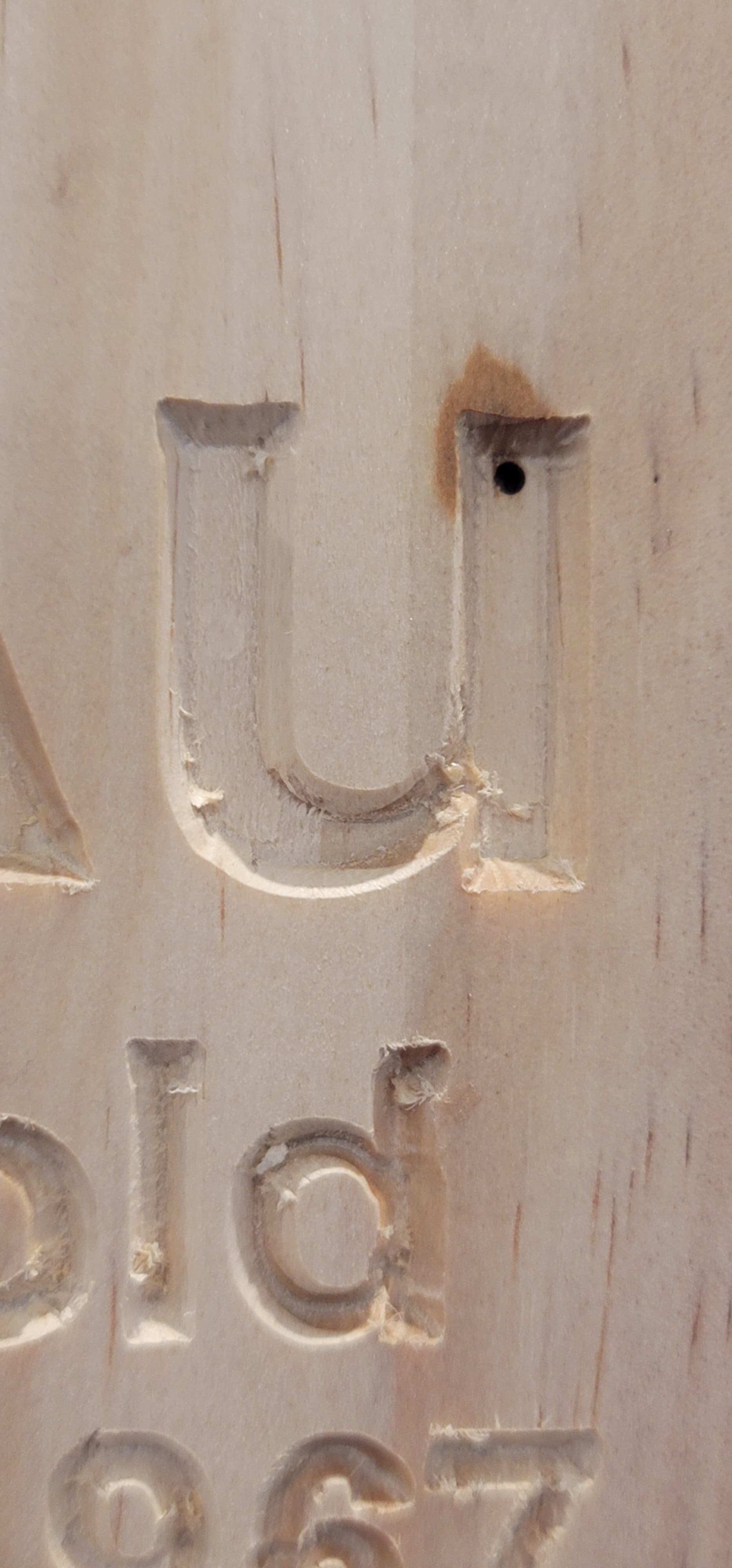
It looks like the VB is carving off of the tool path in the lower left hand side of the “U” & the numbers. Have you looked/verified the bit is tight in the router? Bit or collet is round? Swarf in the collet?
Not gonna lie, i had to look up the word swarf. But no, i just checked, the bits in rock solid, it rotates tightly around the tip, the collet is clean - and thats something i make sure of when i change bits during the process. Thanks for the thought though.
I am sure you know it but something is wrong. On a 3XXXL I did the attached with a 60 degree Vbit. This was a normal V carve tool path in cherry all done with CC/CM. Your machine should do this easily. I did struggle with what you are seeing a year or so ago and never really resolved it, I just gave up and moved on to other projects. I know then I was using poplar (not good for inlays), the letters were much larger than in this sign in cherry, I have surfaced the wasteboard, and I am using a more expensive bit but it still looks like there is a flat on the tip. I zeroed on top. Unfortunately, a lot of untracked variables. I sometimes wonder if larger isn’t more difficult because the flaws are more evident. If I discover something, Ill definitely let you know.
Definitely possible, other than just torquing on it, is there a specific way to evaluate that?
The thing that got me to actually buy this CNC was so I could do inlays, so I’m willing to try about anything to make it work. I’m getting to the point where I’m thinking about taking the whole thing apart and reassembling it.
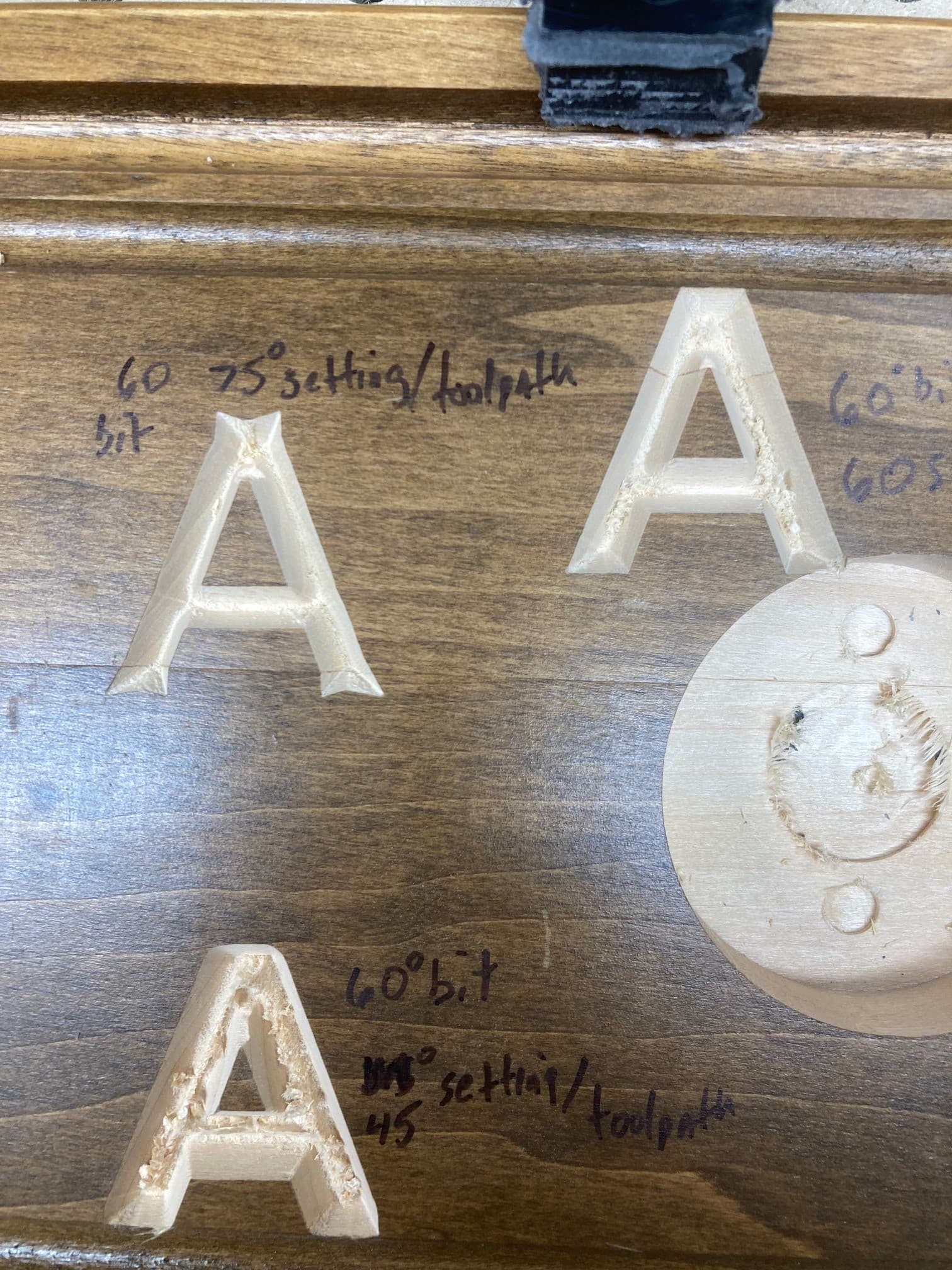
A quick demo using your “A”. I used the same 60 degree bit I used on the previous posted sign. These are only a v carve in poplar with your depth setting. Untouched carvings.
Top right, I told CC the bit was 60 degree, so a 60 degree toolpath/60 degree bit. Looks decent.
Top left, I told CC it was a 75 degree bit, so the tool path was for 75 degree but used a 60 degree bit (bit 15 degrees less than CC expected). Path is not deep enough.
Bottom, bit was 15 degrees more than CC expected. Path too deep.
I am not so sure this is even meaningful. Because the toolpaths CC created are different for each angle. I will retry by just modifying zero all with 60 degree paths…
Your “A” looks so much better than mine. That seems to suggest there’s a problem in my machine/bit. Thank you for doing that, it at least narrows down where I need to be focusing.
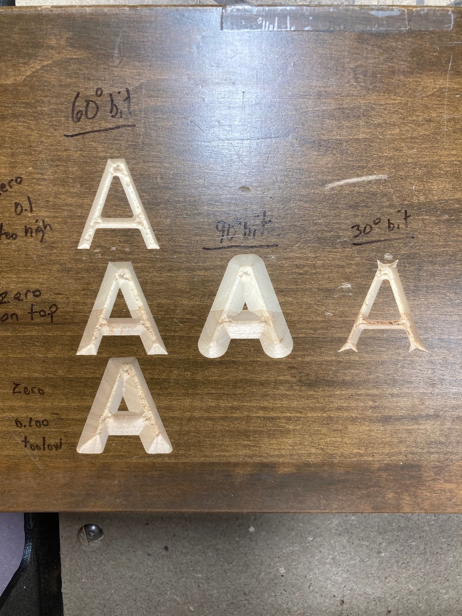
Here is a more meaningful evaluation of errors in bit angles and errors in zero.The are all done with the same 60 degree v carve tool path from CC in poplar. Your A and your depth of cut setting. I did not monkey with any of CCs settings which were for hardwood (maybe not the best choice with poplar). Column 1 is a 60 degree bit with variable errors in zeroing. Column 2 is a 90 degree bit, no intentional error in z. Column 3 is a 30 degree bit, no intentional error in z. These errors should be huge compared to what one could accidentally get unless you used the incorrect bit. What I find the most interesting is the sharpness of the outside perimeter corners compared to the inside perimeter corners. For the 60 degree bit, a zero too high rounded the inside perimeter corners, a zero too low rounded the outside perimeter corners. A bit whose actual angle was wider (90) than the tool the tool path was made for (60), rounded the outside corners but not the inside corners. A bit much sharper (30) than the tool path (60), gave wings on the outside corners and rounded the inside corners. Interpolating these might give a hint to the source of a problem if it is related to errors in zero and /or bit angle. I set all my zeros here on the top with the paper method. (I dont have the bit setter/runner things). You might try stepping back from the advanced v carve (which I did not use) and just try a v carve to see how/ if your results change. Troubleshoot that before adding in the advanced v carve and bit setter/bit runner things.
Thanks, ill give that a shot. Im working for the next couple days, and my job is pretty all consuming when im on, so ill try it later this week and get back to you.
Random thought, does anyone have an inlay pocket file they know works and would be willing to share? I was thinking if i could just run g code that i know works on someone else’s machine, with the same bit and settings, it could help further isolate my issue.