So unable to leave well enough alone, I’ve taken things one step further…
The rulers are definitely nice. But they don’t help much when I want to measure a dimension that’s not horizontal or vertical.
So I spent the slow day at the office today creating a small app of my own that allows you to measure the distance between any 2 points in a CC drawing.
Step 1:
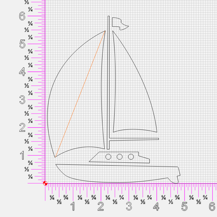
Use the polyline tool to create a straight line between the 2 points in the diagram where you want to measure the distance.
In this case we’re measuring the point-to-point distance on the main sail. Why? Because every sailor knows that’s important to know… er something like that.
Step 2:
Make sure the polyline is selected, and in the ‘Move’ section select one of the left points of the bounding box. If your line slopes from SW to NE, then select the lower left(SW) corner. If it slopes the opposite direction(NW to SE) then select the NW corner.
If it’s a horizontal or vertical line, pick either. Though in that case just using a ruler would probably be easier.
So based on the example diagram here, we’d select the lower left(SW) point.
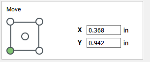
This gives you your starting XY coordinates.
Step 3:
In the same ‘Move’ box select the end point of the bounding box.
This would be the opposite corner of what you selected in step 2.
In my example, we’d select the upper right(NE) point.
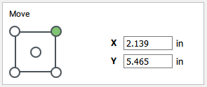
This gives you your ending XY coordinates.
Step 4:
Plug the XY coordinate values into the handy dandy CC_tape_measure tool.
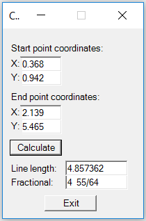
and voila!
There’s your length measurement. Both in decimal and fractional (rounded to the nearest 64th)
Of course if you’re using metric, just ignore the fractional output.
I cobbled this together in powershell, and am including the source along with the exe. It’s been fully tested! Well at least tested enough to remove my typos and division by zero bugs.
The actual computation part is just a few lines, the rest of the script is all the GUI junk. So if you’re inclined, feel free to re-write in Python, C#, COBOL, or whatever floats your boat.
If you start a multi-million dollar business with it and get a Shark Tank deal, I require a 30% equity stake in your company. 
CC_tape_measure_v0.3.zip (11.9 KB)