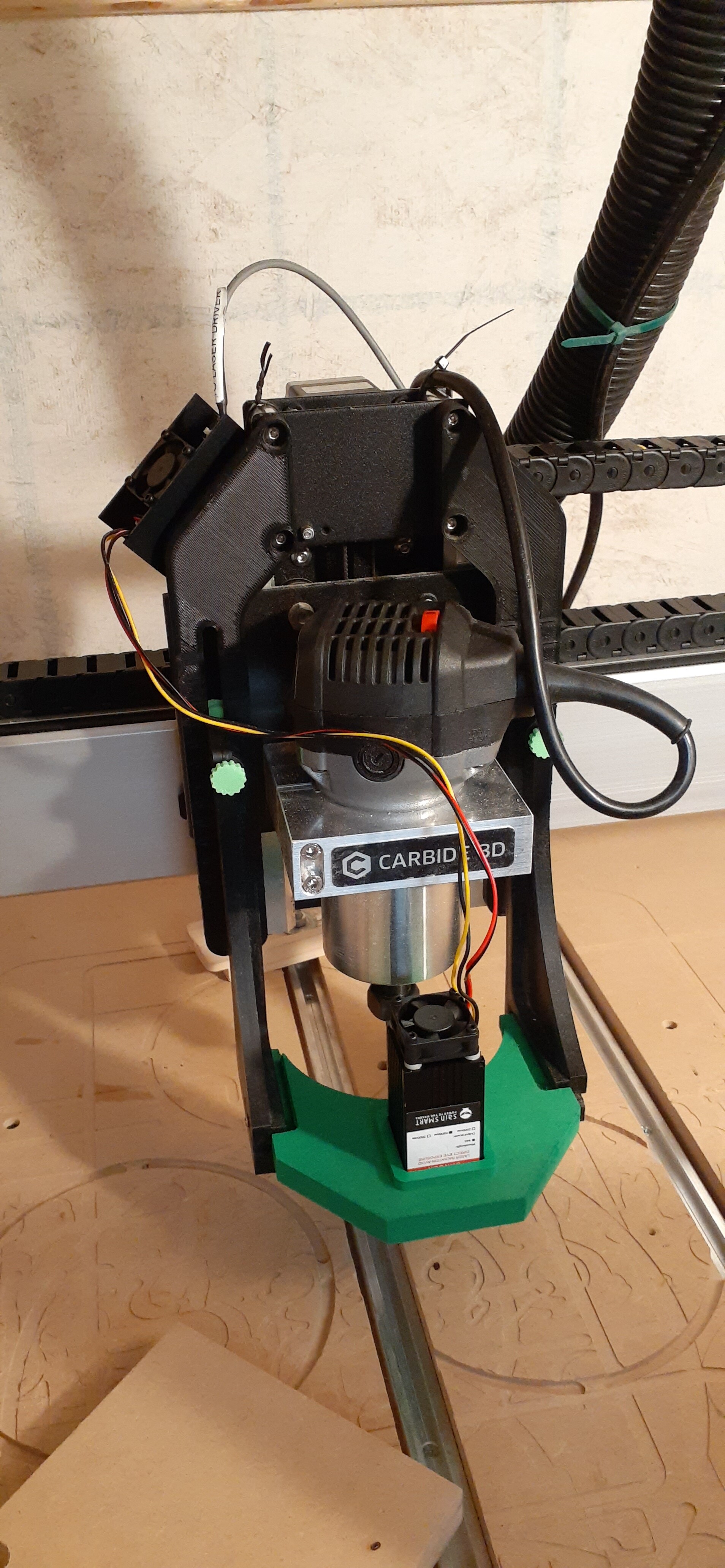
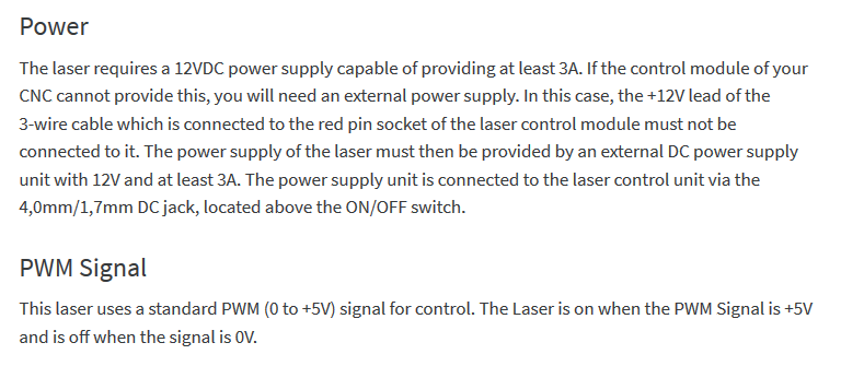
Dipped into the laser world and am hooking up a sainsmart laser to my xxl. Wired it into the board and ran the wires per some instructions that came with it, then got lightburn all setup.
Issue I am having is when I hit the power button on the laser it is always on. I tried to search some and it may be related to PWM signal from what I read but not sure so wanted to ask before i went further.
Any help would be appreciated. Here’s some pictures for reference.
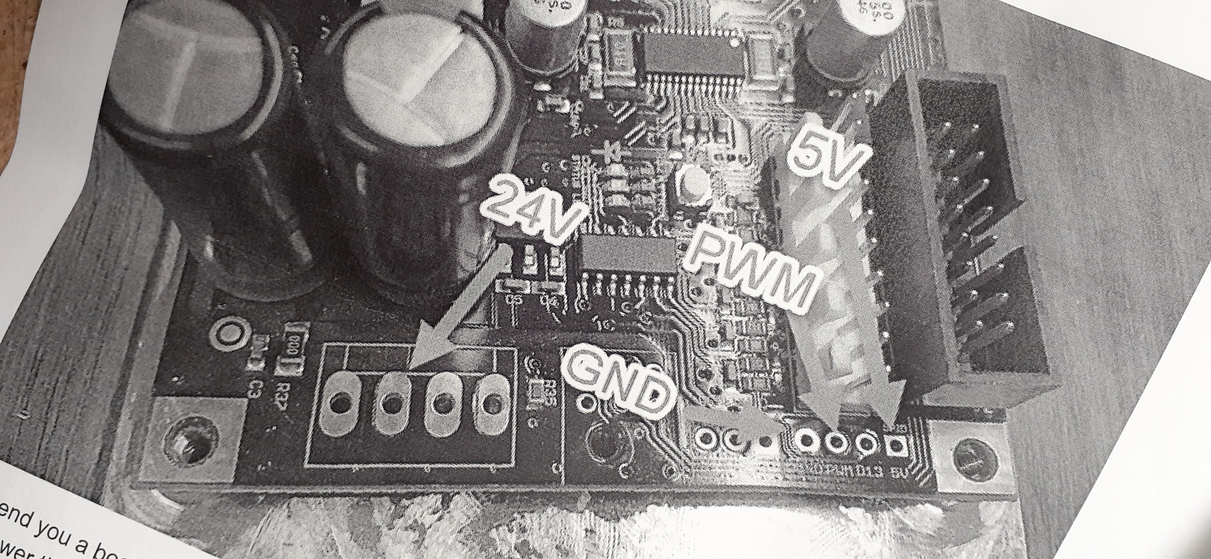
If you have a voltmeter, check the voltage between PWM and GND at the laser side at power on. If it reads ~0V, then you’ll know it’s not the PWM and it must be a setting on the laser itself. Does it have multiple operating modes and many one of them is to ignore the PWM? (the Jtech laser has a “manual” mode like that).
So I unplugged the “to laser driver” plug and turned the main power switch on. I used my voltmeter and put my red side into the PWM and the black into the ground. I got 10volts reading on Vac setting.
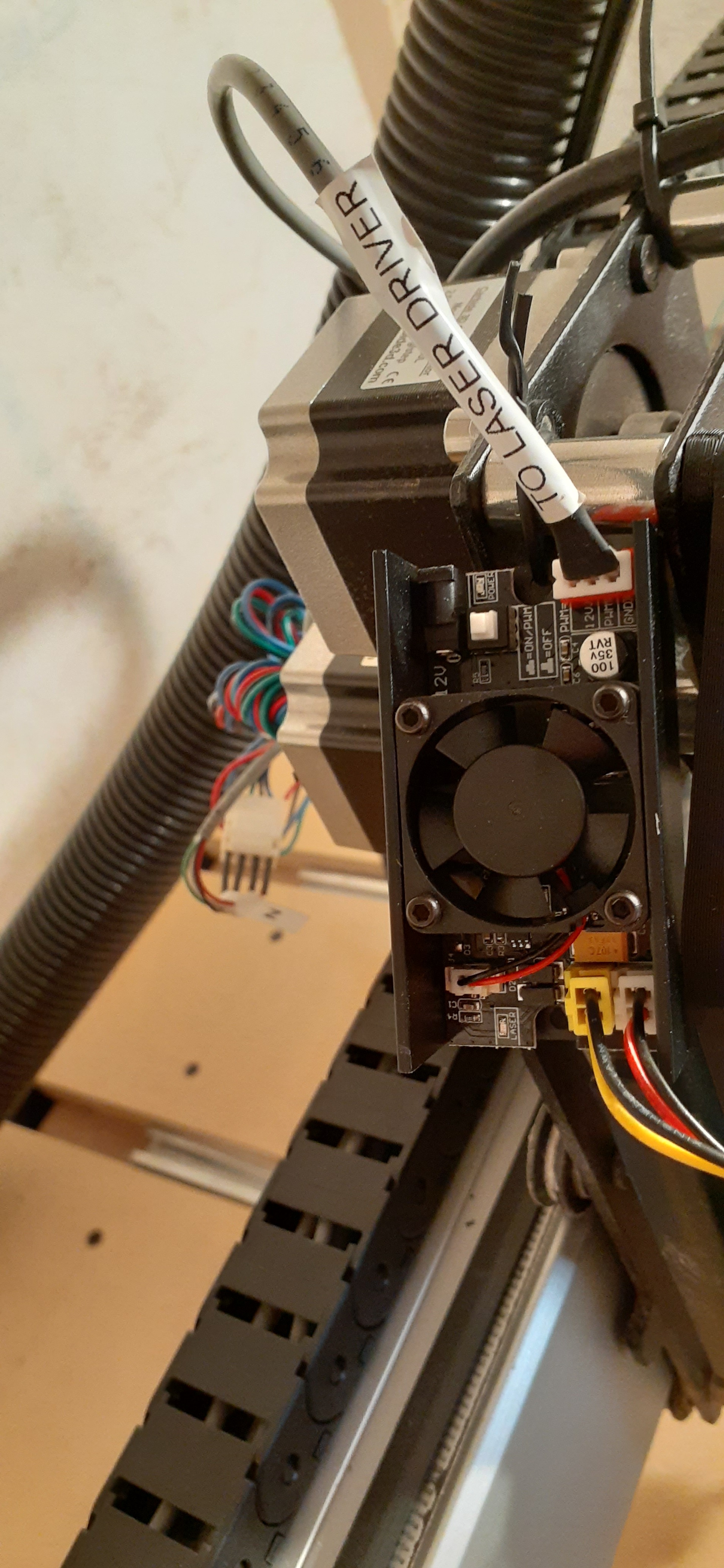
I then plugged that in, pushed the PWM button to the left of it in that same picture and the power led turns on. I unplugged the yellow and black cable that is the laser and used my voltmeter again. I got 14.6volts.
In my first post I mistook my power on/off as that PWM on/off. After reading the instructions further I wanted to clarify that. The instructions say I want PWM on but when I do it fires the laser all the time.
it should be Vdc for that measurement (continuous), but anyway I don’t know what that Sainsmart board does with the 0-5V PWM signal it gets from the Shapeoko controller board and it’s hard to tell from the pics which bit goes from where to where. Do you have the assembly instructions in digital format and it is shareable here ? I’ll log off for the night, happy to have a look tomorrow, but I guess in the meantime someone who actually uses the same laser will chime in.
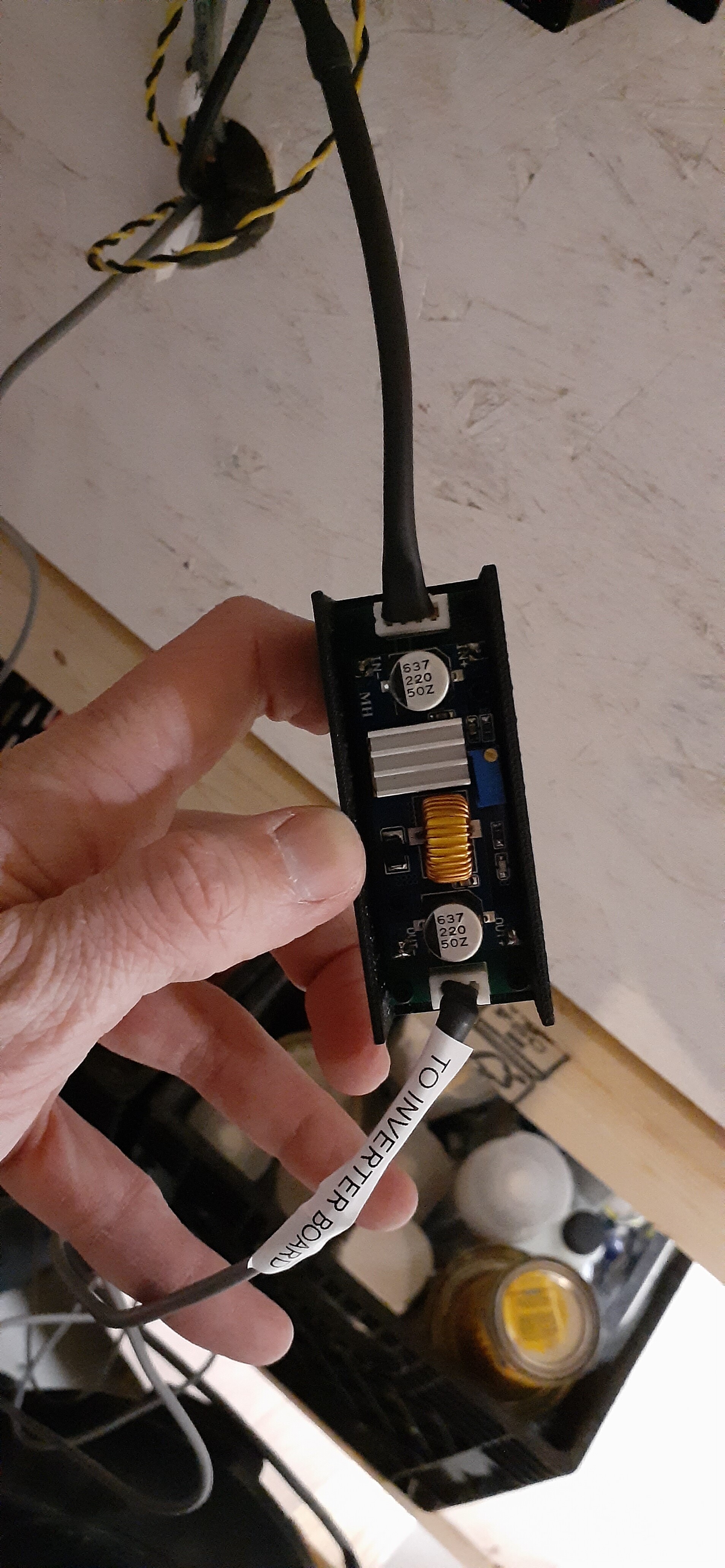
After looking over these I learned included with the package I purchased was an aftermarket PWM inverter. This took the signal from the Shapeoko board and converted it from 0 to 5. I measured prior to this inverter and got results of 0 Vdc and after the board it was 5Vdc. This was the reason the laser was always in the “fire” state I assume.
So one question is does a shapeoko require an inverted PWM signal? If not I can take this portion out and wire the laser up per the instructions from the link I sent. I tried to do this tonight and had to rewire the connector to make this happen. I then turned on the Shapeoko and using lightburn homed the machine, which worked properly. I was also able to use the move features to move around. Knowing that worked I then pushed the PWM button on the laser driver to the “on” position. The led power light turned on as planned, laser did not fire as it had before, but it appeared very weak as the LED was flickering and would not fire the laser when I pushed the fire button in lightburn. It was at this point and confirmed with my voltmeter I realized the laser was only getting 5V instead of 12V.
So I guess my next question is where would I get 12V from the board to connect the laser to? I tried searching for schematics on the board but didn’t come up with much.
Do you think I am on the right track with this or does it still seem im lost?
First I’ll just make a “disclaimer/reminder” that hooking up a laser is not a supported mod, so if you are unsure about the steps you are taking, well just be extra careful, we wouldn’t want you to mess up your Shapeoko controller board and I’m afraid C3D support may not…support you then. But as far as I am concerned I’m happy to try and help you troubleshoot.
I had a look at those instructions, and two parts stood out:
So these are the operating modes I was referring to, keep this button pressed in the “On/PWM” position (and it must have been in the “OFF” position before and that’s why you got the always-on laser)
There is no 12V available at the Shapeoko controller, and even if there was it would be a Really Bad™ idea to pick it up there, because that laser draws 3 amps on that 12V input. You definitely need a standalone 12V/3A power supply brick, with a jack connector matching the type on the laser controller
The documentation confirms that the laser controller expects a 0 to 5V signal on the PWM, which is exactly what the Shapeoko controller generates, so I can’t imagine why there would need to be an inverter between the two.
I did not get where you picked up the 12V before ?
The expected behavior once everything is setup correctly (standalone 12V/3A power supply connected to laser controller jack connector, Shapeoko’s PWM and GND connected to laser controller’s PWM and GND input, push button in the “ON/PWM” position) should be this:
at power up, nothing happens, PWM is close to 0V, laser does not light up, not even a little bit.
after initializing the Shapeoko if you then send an M3 command from the MDI with a specific RPM value to “start the spindle” (which will actually start generating the PWM at a given average voltage, reflecting the RPM value), only then should the laser be active, at an intensity that depends on the RPM you set in the M3 command, and which also depends on the value of GRBL setting $30 (the RPMs from 0 to [the value in $30] are mapped to RPM voltages between 0 and 5V. So commanding 500 RPM would generate a 2.5V PWM for example, if $30 is 1000.
I think Julien’s interpretation of the instructions is correct.
You need an external power pack plugged in to the black power socket above the switch, the PWM button pushed in, and the PWM and GND pins from the red connector going to the Shapeoko controller.
The inverter seems to be there to cope with some 3018 Pro CNC boards that used to have the PWM logic inverted, so probably is of no use here.
Thank you for the response again. I will search around today for a 12vdc 3a power supply.
The laser was getting its power via the 24v pin on the control board prior and then through that inverter box. It appears the inverter box did the PWM signal change and also converted that 24v to 12v and sent it to the laser so there was no external power supply.
I also understand that it is not supported, that’s why it took me 3 years to finally decide on it I think.
I emailed Tony and learned he was running the laser with the PWM in the off position somehow and also learned I could add a wire to the inverter box he built to keep the PWM signal at 0 as the shapeoko puts out instead of inverting it. Doing this would still allow me to use the box he built to reduce the voltage and power the laser all from the shapeoko control board. In the end I wasn’t comfortable messing with the wiring and based upon sainsmart recommendations to always keep the PWM in the on position I decided to take the inverter box out.
I went along and ordered a stand alone power supply that should be here Sunday and plug directly into the laser control unit. I will get that installed and update again so others will know if they go this route or maybe I’ll need more help, well see.