I’ve just imported a DXF to Carbide Create and it came in bigger than it should be (must be something to do with how I’m creating them I think - metric/inch issues. I’ll look into it when I have more time). Anyway, I scaled it to a height of 73mm, which is what it should be. I hit enter; it scales and looks about right, so I apply my toolpaths and do about an hour of machining only to find the finished part is ~72mm! When I went back into CC I selected it all and found it was actually 72.314mm high! WTF!!! Thinking I’d made some daft error I re-imported it but the same happens…
If I scale to 73 hit apply, then scale to 73 again it bumps up to 72.952 but further scaling has no effect. What the hell is going on?! This is the second time I’ve been caught out with this same issue, which has wasted a chunk of material.
Apologies for the frustrated tone, but tomorrow is deadline day and right now it’s not looking good. I hate missing deadlines.
OK, I’ve been playing with settings since my first post and I’m confused… I output DXFs of the same 73mm part from SolidWorks in a couple of different ways and each time I imported to CC they came in at 1854.2mm which is 73 INCHES. I checked my CC settings and they’re definitely mm. I opened the same DXF’s in DraftSight and can verify that they’re metric - 73mm as expected, so I don’t think it’s SolidWorks. Plus the fact I send out countless DXF’s for laser cutting every month with no complaints…
Why on earth when I open the same DXF in CC does it jump to inches?
Unfortunately, DXF doesn’t communicate units — it just assumes.
I always put a rectangle of known dimensions around everything, then when I import, check the size of the rectangle and everything in it — if it needs to be adjusted, it’s a single change.
My current part is basically a rectangle measuring 73 x 100mm (with a few counter-bored holes and plain holes in it) so I already know how big it is/should be. If I add a rectangle, all that will happen is that when I import to CC it will all be 25.4x too big: it’s when I scale that the issue comes in. Scaling in CC (as far as I can tell) does not do what I’m asking it to.
If you place a rectangle of known dimension around everything, import the DXF incl. the rectangle, and then set the rectangle (and all of its contents) to the correct size, does that not work?
Nope. Same. I’ve included a screenshot so you can see what I mean about my original part - it’s basically a rectangle anyway. I drew an 83 x 110mm rectangle around it (5mm offset around my part), saved and imported it, scaled it and as you can see when I reselect it and hit scale again, it’s not to the figure I typed.
Send the following to you by way of your support ticket — hope you don’t object to my sharing it here.
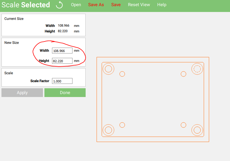
Okay, I imported your DXF, and attempted to scale it to 110mm x 83mm — this results in a size of 108.966mm x 82.220mm
Applying the dimension a second time (scaling factor of 1.009) gets us to 109.947 x 82.960 which is 99.9518182% of the desired size and would require a scaling factor of 1.00048205 — which is finer than the 3 digits of precision which Carbide Create affords.
Opening it up in Inkscape allows one to set the size to 110mm wide, which when imported into Carbide Create imports at 146.667mm, which when scaled to 0.75 or sized to a width of 110mm is the correct size (except that some lines were dropped).
Repeating this by first closing up all the paths yields the attached file.
I’m referring your ticket to a developer and we’ll try to have one look into it.
No problem - hopefully others will benefit from the dialogue.
Building on your idea of pre-scaling before import, I tried scaling my dxf in DraftSight by 0.0393700787401575 so that when I opened it in CC and increased by 25.4 it would be correct… It worked perfectly: my part is now correct to .00mm. With either method, I’m much happier now I have a viable workaround.
I think the issue is with CC ‘assuming’ (I hate that word) that my part is imperial, even though I have units set to mm. DXF’s are unitless as you rightly say, so when brought into a program should adopt the units the program is set to.
I look forward to any feedback from your developers.