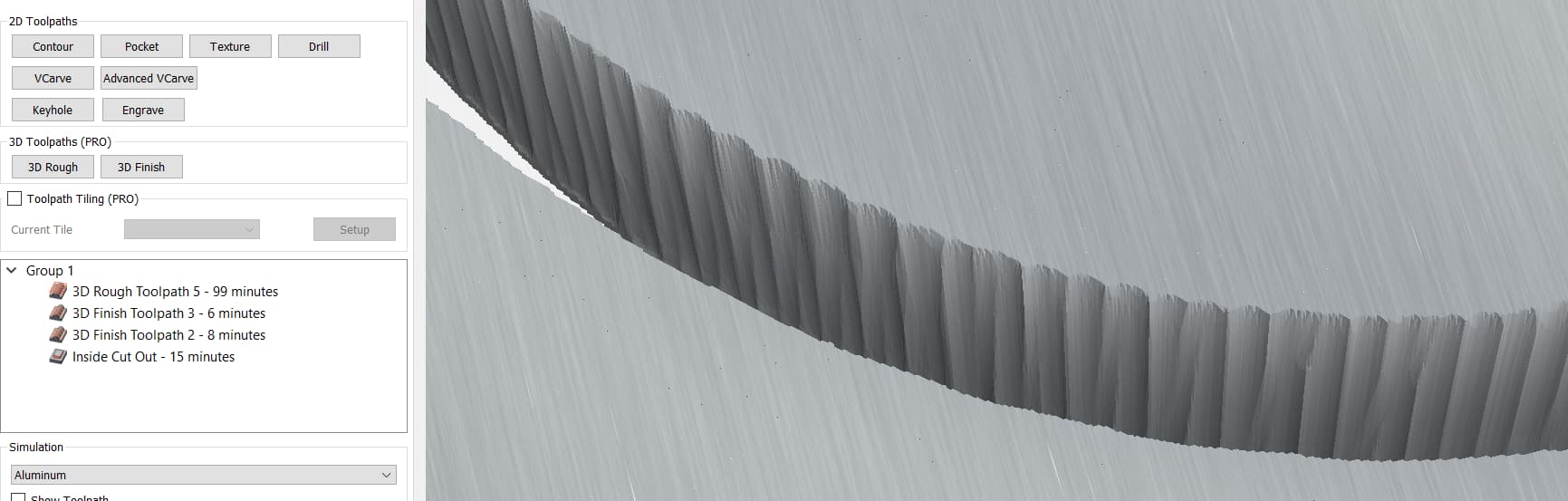
When I do a finish toolpath a ball bit, it’s creating this scalloped surface that is not supposed to be there. I’ve tried changing the stepover (made .22, .125, .05, .005) and the results are roughly the same (except the smaller stepover takes a lot more time…but the scallops are still there).
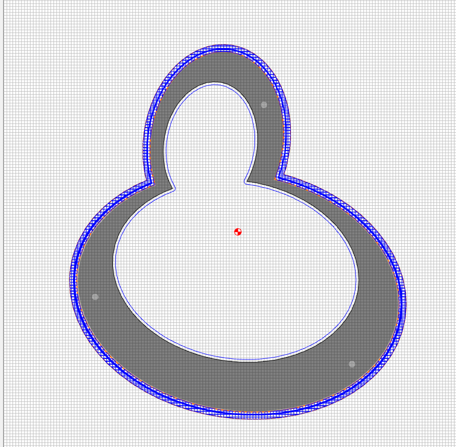
I tried making two finishing passes at 90 degrees to each other…and the result is still the same:
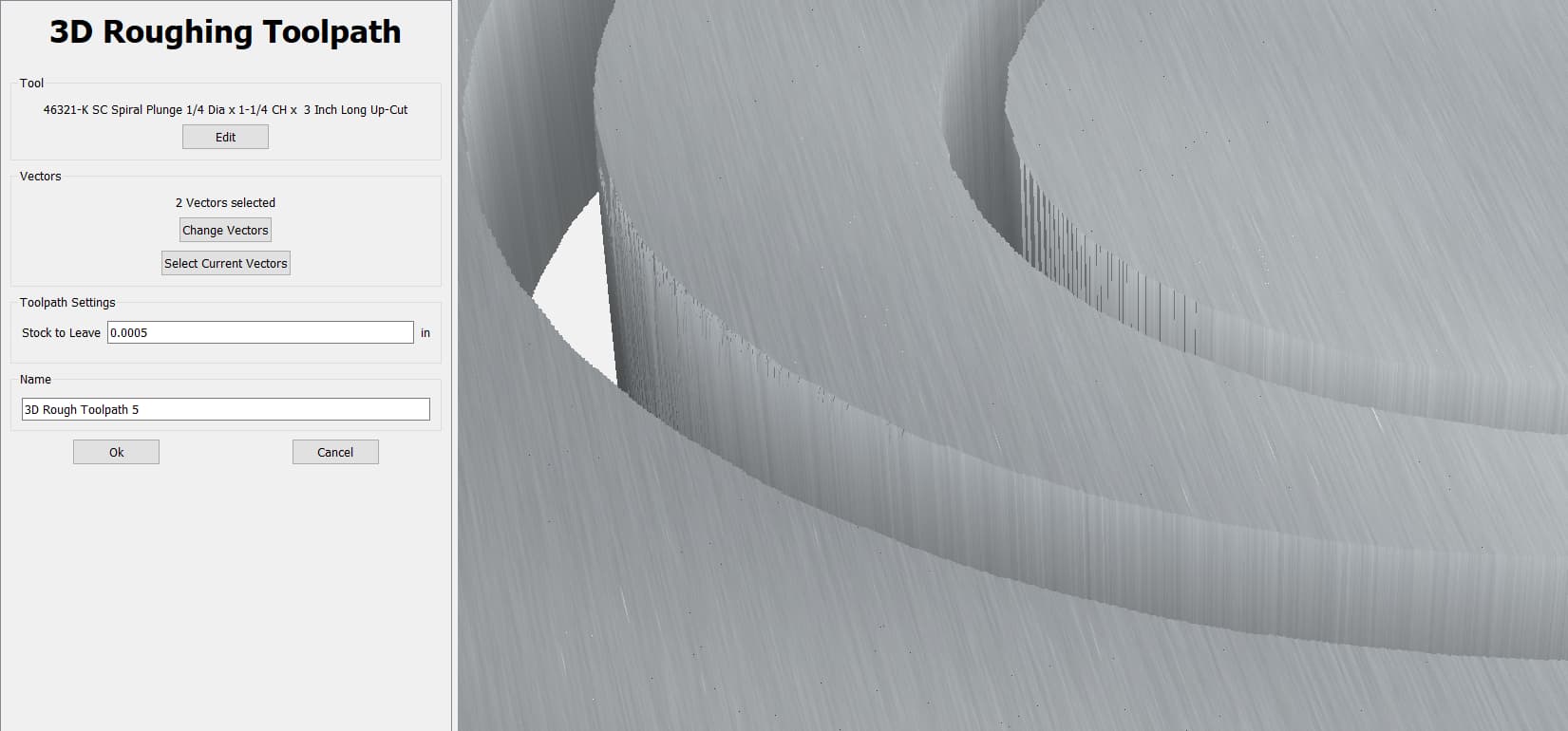
The idea behind the large Depth per Pass is to avoid a lot of time making small cuts.
The reason not to start with a small value for Stock to Leave is to avoid the roughing operation chipping something out or deflecting into the part itself and leaving a gouge.
Yes, the simulation assumes that the cut is executed without error and doesn’t take into account the possibility of the stock chipping or the tool deflecting.
Well, damage it in some small way, unless a chip was really large.
The scallops are in the vertical section, not the bevel right?
I had something similar when cutting a 3D part. Seems like I ended up creating a tiny offset inside and having that limit the 3D cut. Then used a profile to clean up around the outside.
Or maybe adjust the 3D model to have a flat area at the level of the lower edge of the bevel. So that the ball nose doesn’t fall off the edge. Then do your profile.
Maybe I am not interpreting the problem correctly.