Please don’t let my unwillingness to touch Autodesk products limit your own choices — Fusion 360 even nerfed as it is for the current hobbyist license has a lot of nice features and for folks willing to use it is probably a good option, even for such simple tasks.
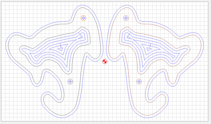
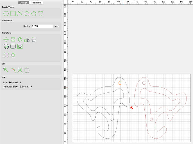
OK, so I took Will’s trace and after some tweaking of that, recreated the file:
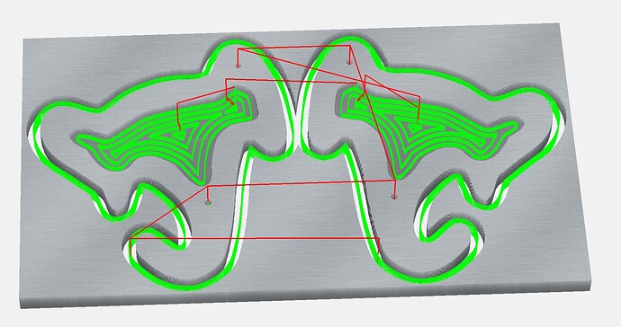
Note that I smoothed some sections out, rotated to get the grain orientation I wanted (vertical), inset the pocket manually rather than with an offset, and added two alignment holes. Here’s the simulation:
Note in the above that the alignment holes are ⅛" in diameter, which isn’t what I specified:
I don’t know what’s going on here, but I was OK with ⅛" diameter holes instead. Can anyone explain for me?
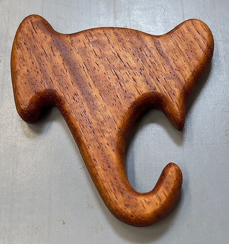
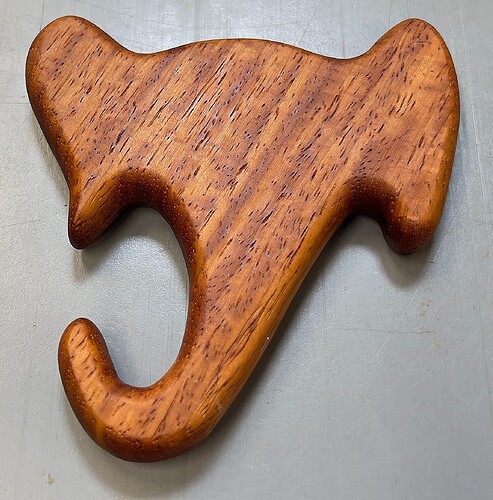
The first rattle turned out great:
And notice the resaw enabled pretty decent grain matching on the edges:
The alignment holes make all the difference - glue up was painless and perfectly aligned, so only a light sanding was needed to remove excess glue squeeze out, then round over all the edges on the router table, then finish sand everything. Using a pure tung oil (food safe) finish.
Thanks!
PS: Making Will’s first post as “Solution” since it basically was.
PPS: Carbide Create was great to use for this project. Simpler than Fusion 360 and the ability to easily modify the depth of the toolpaths meant I could dial in exactly how deep to cut the contour out. I was actually able to just touch the first layer of blue tape leaving an unmarred MDF piece underneath.
Did you drill 1/4" holes with an 1/8" tool?
The drill toolpath doesn’t care what size the drawn circle is, it only uses the center point.
In fact, you can select a non-circular vector & it will drill a hole at the geometric center (The center of a rectangular bounding box)
Ah, that explains it - thanks.
This topic was automatically closed 30 days after the last reply. New replies are no longer allowed.
