I’ve looked around with no luck in finding a way to design a semi circle cigar rest into my cigar ashtray designs. On other projects I’ve done I’ve used a Forstner bit but I’m looking to develop the skill rather than buying the file and making someone else’s idea. I’d like to use the 3D feature in Pro rather than just creating a toolpath for a cove bit. I believe its a simple thing, I just need to learn to do it for myself. Anyone willing to pass on their knowlege?
with the modeling tab you can do this. you first need to create some stock geometry then subtract a round feature.
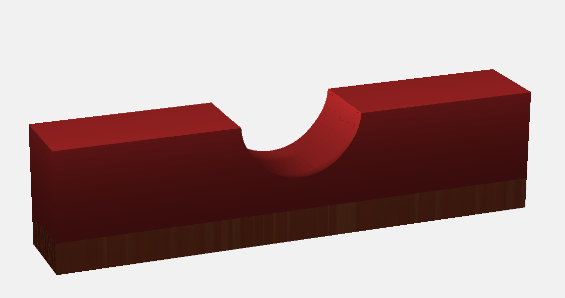
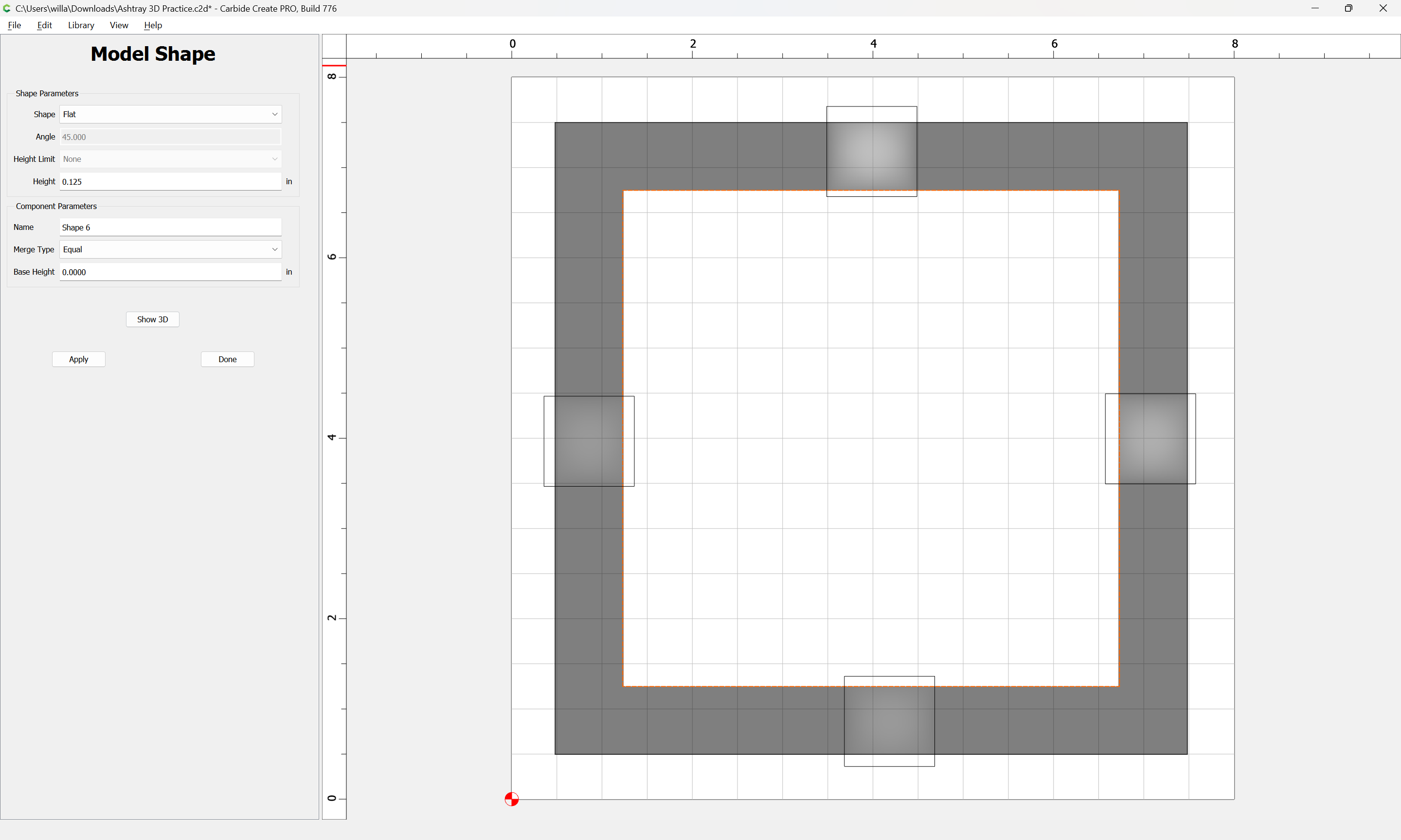
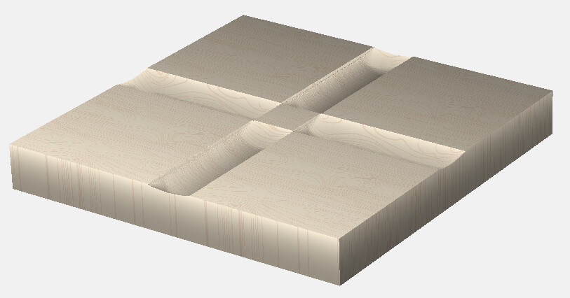
Note the round feature is circular so if you want cleaner edges so it looks like a semi circle you need to extend the base block out from each side of the material like so.
was that cryptic enough? hopefully it will get you going, if you need more info let me know.
1 Like
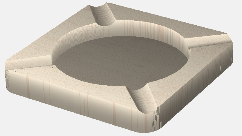
Given a design:
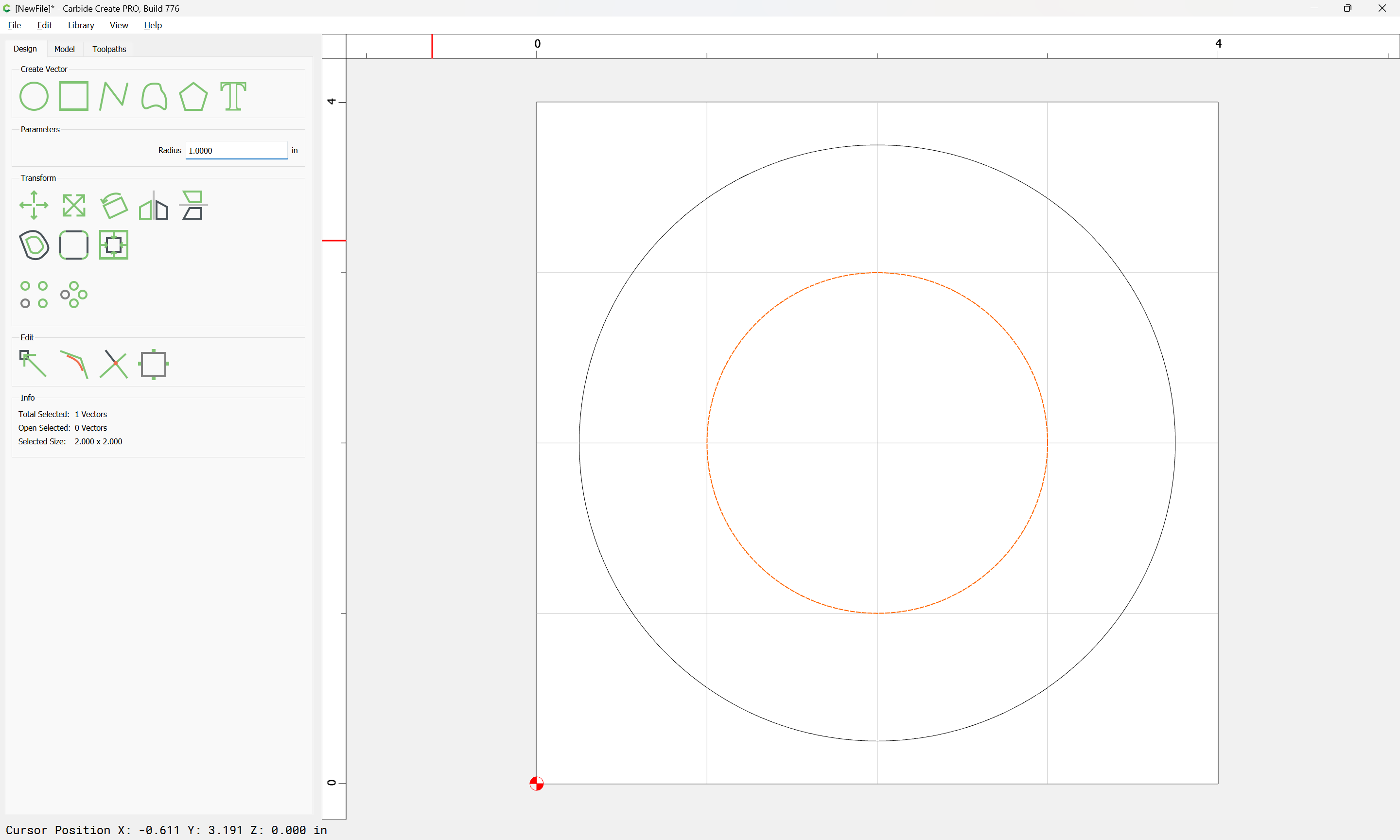
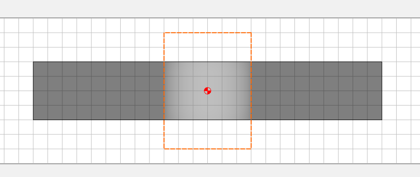
To get a cigar rest into this, draw in a rectangle which is larger than the object:
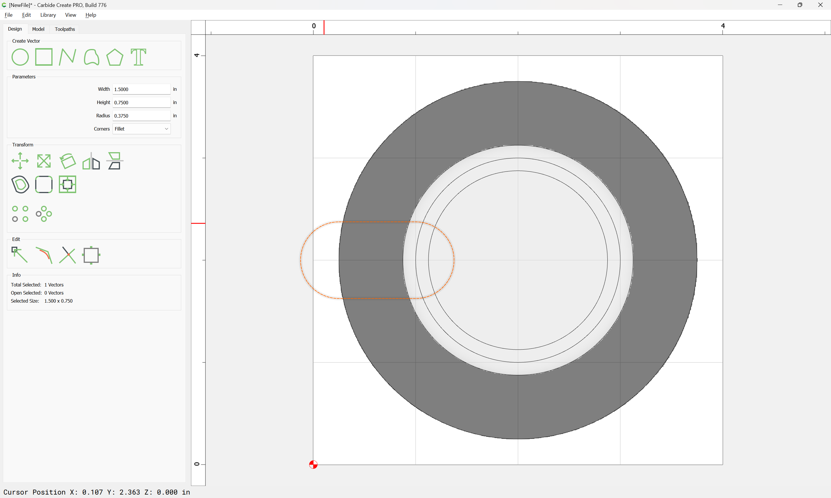
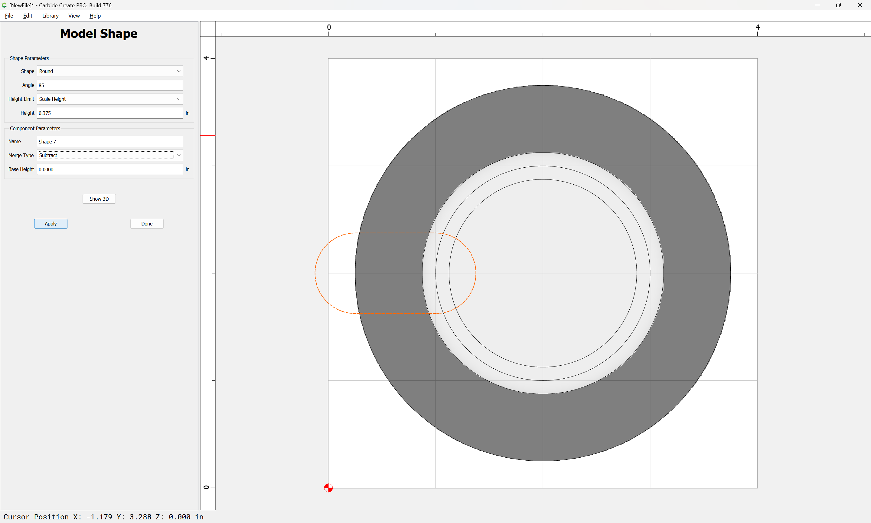
and insert it into the 3D Model as a subtracted object:
Attached as a v7 file.
cigar_ashtray.c2d (252 KB)
Is there a video tutorial that explains the Model tab? I’m getting lost when it gets to that tab.
Do you know of any video that explain this? It may be easier for me to pickup.
Ashtray 3D Practice.c2d (124 KB)
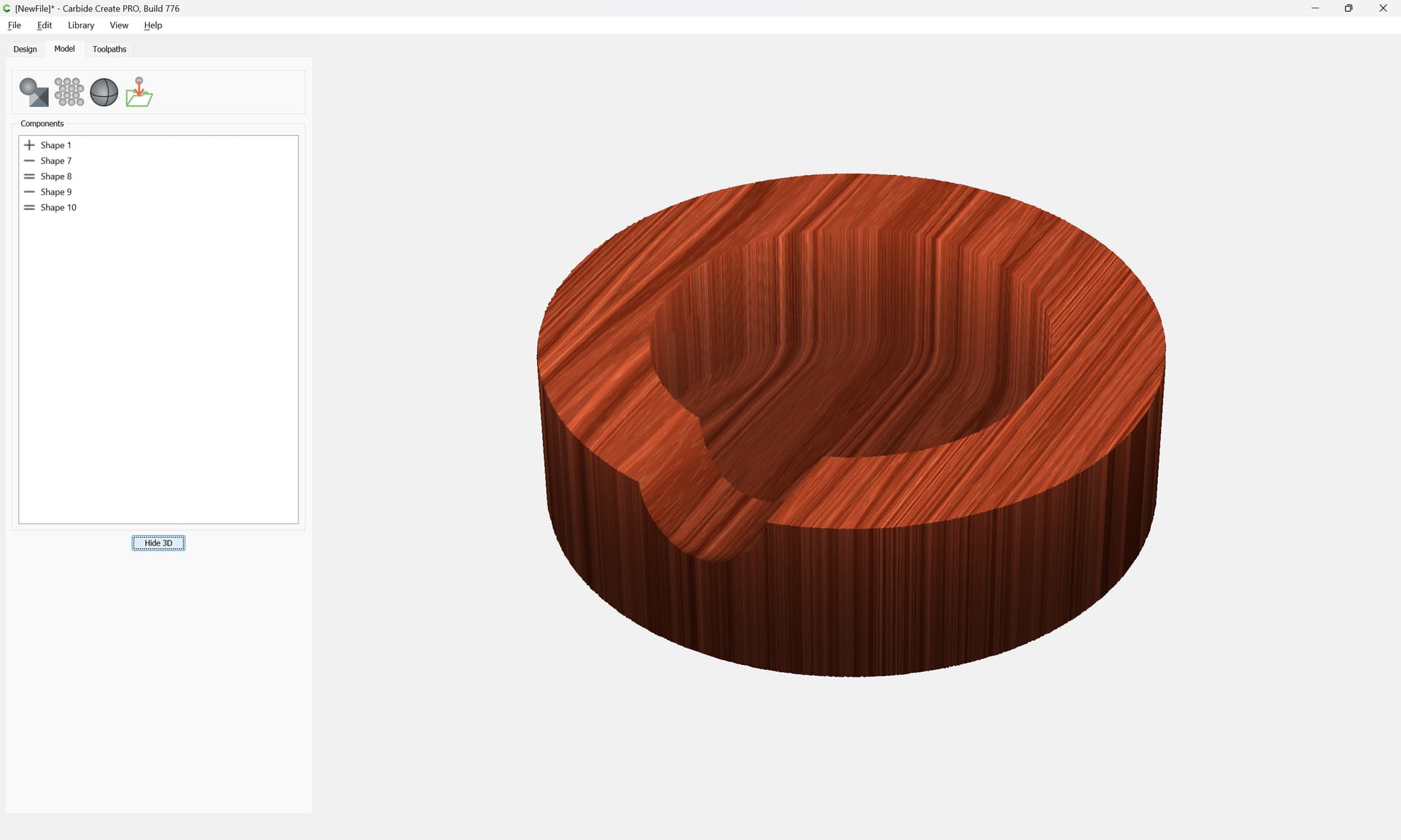
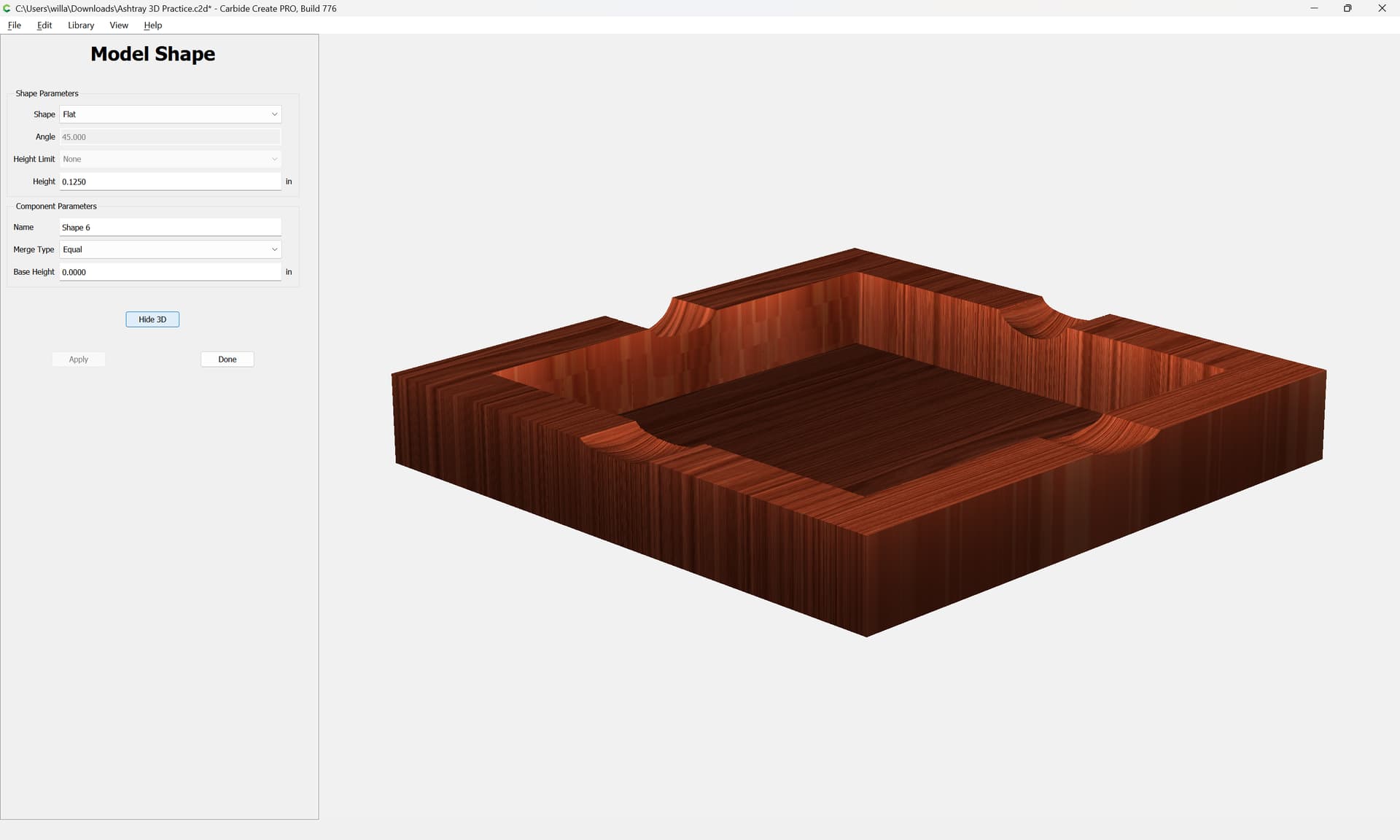
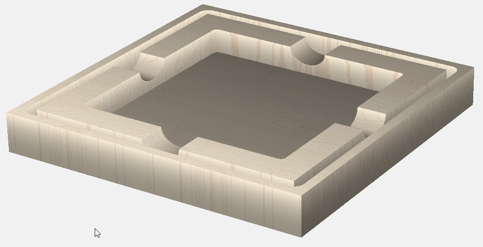
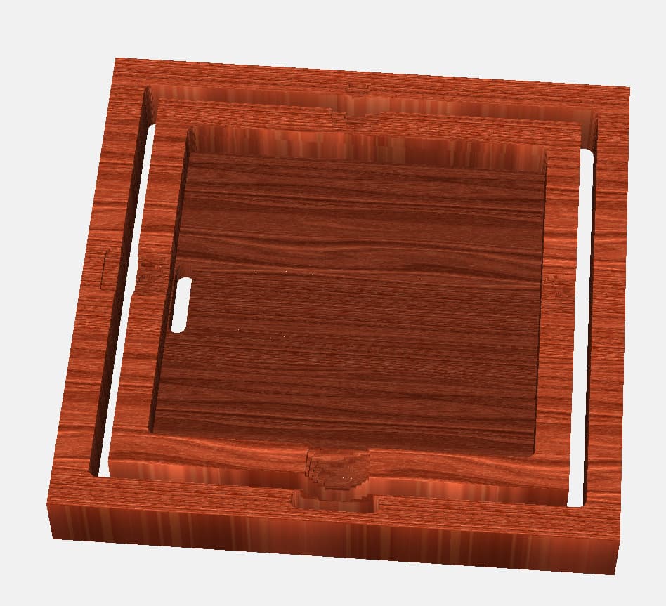
I’m starting to get the hang of it. What is causing the slot/hole in the inside pocket?
I used different settings on each rest practicing how to get different depths. I’ll keep practicing while I’m at work and get on the machine once I get home next week.
The geometry needs to be sufficiently past the edges to allow it to model in its entirety.
I did notice that. I made the rectangles shorter in an attempt to cut down on time, but I did see how it effects the geometry. Maybe the hole in the bottom is a glitch and will not show up in the actually job.
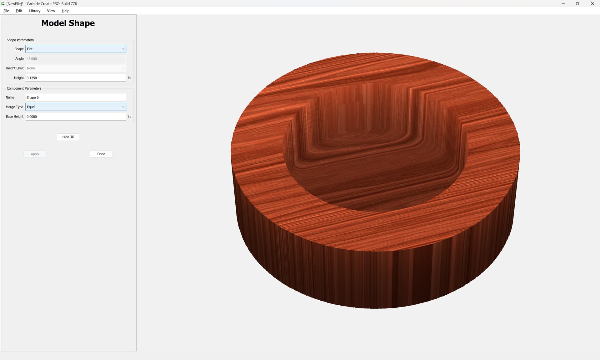
The hole in the bottom is because of how you modeled.
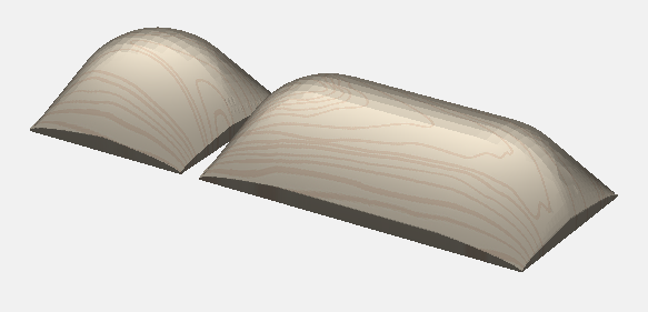
You need to restore it by selecting that geometry:
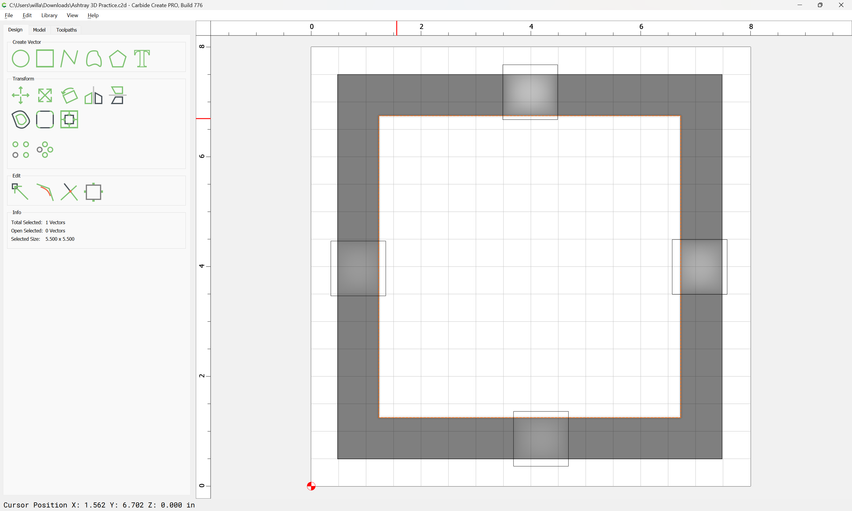
and then modeling it to be the desired thickness:
1 Like
When you make a round component it creates a rounded shape from all edges of the vector, including the ends. There is no “cylinder” component. So you need to make the ends at least 1/2 as long as the shape is wide. Your shape is 1" wide so the ends need to hang out at least 1/2".
The hole in the middle doesn’t matter, since you are cutting that feature with 2D, which doesn’t look at the 3D model. All you really need to model is the curved rests. The rest of the model doesn’t matter unless you want the “Show 3D” to accurately represent the part for show. Like to send a customer for approval.
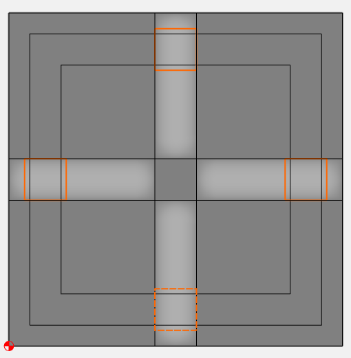
Here I created an extra outside rectangle, and 2 long rectangles for the rests.
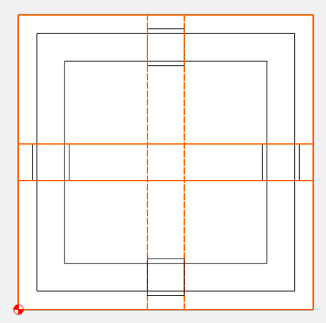
I created a flat, 1" height component from the outside rectangle and Added it.
I created a round, 90° angle, 0.375 Scaled height from the rest rectangles and Subtracted them.
The raised bit in the center also doesn’t matter…
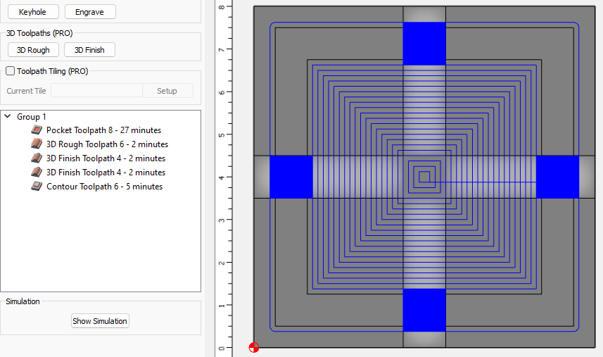
Now select your smaller rectangles for the rests to machine them.
I used 2 finish toolpaths, one for the horizontal rests with an angle of 0.0, and one for the vertical rests with an angle of 90 so both cut along the axis of the cylinder
Ashtray 3D Practice Tod.c2d (156 KB)
2 Likes
Now for the real world aspect of your project.
- Cigar aficionados abhor sharp edges.
- Cigar aficionados abhor leaning their cigar into ashes.
- Cigar aficionados don’t want to taste the ashtray.
- Cigars have many diameters (ring), lengths and several shapes.
- Cigars have variable balance points.
That ought to change your design. ![]()
1 Like
Ordering of the 3D operations.
You need to have an == to the bottom thickness as an operation after the indent is made, and it has to be created after the indent is made (note that this may change in a future version as noted in recent discussions here).
This design was a very rough “design” so that I could work on designing the rests. This will be the first time I do something like this on a cnc, I typically use other tools to build them for family and friends, just trying to build another skill set.
I agree with you bullet points 100%.
1 Like
In the rough 3D toolpath, the tool is falling off the side of the model because there is nothing there.
Think of the job in 2 steps… cut the 3D features independently of the 2D features, and make sure there is extra stock around the 3D model so the tool has somewhere to go.
2 Likes
This topic was automatically closed 30 days after the last reply. New replies are no longer allowed.