Hi guys, so I finally figured out one of the issues that was happening where my machine would just start missing the wood by a few inches.
I believe if I set zero, while Carbide motion is already open with the file that ends up having the wrong home point even know my machine when asked to go to With Home point is dead on?
So is that true and you can only set zero before you open the program?
Correct. Origin is set before running the program, and there is no access to those controls while a file is being sent.
Stop, quit, restart things to get to a known state.
It sounds like he’s asking, “before hitting Start”. i.e.
- Initialize
- Load Program
- Set zero
OR
- Initialize
- Set zero
- Load Program
I’m not aware of anything that would cause the zero to change when loading a program. Or why you wouldn’t want to set zero after loading a program. I’ve done it both ways & it seems to make no difference.
I’ve had my bitsetter off for quite some time now. Unplugged & disabled it to surface the spoilboard, and just never turned it back on. With the bitsetter, changing the tool without measuring it will cause problems. So if you initialize, and it measures the tool in the spindle, then you change tool & set your zero (regardless of whether a file is loaded), then run a program that measures the tool, your Z will be off.
I had a post maybe around a week ago because I could not for the life of me. Figure out why my machine kept missing the wood and I’m still not 100% sure why.
But I did notice that both times it happened when I reset my zeros it’s possible it was also the XY and z. But no matter what I do, including shutting off my CNC machine and my computer and unplugging the CNC machine. It would have the same problem again and completely miss my Wood and then I realized if I have the program not opened when I make my new home point and set zero again then it’s all OK and this is why I was very hesitant to use the top as my zero because it causes about 10 minutes of work extra before a project and all of the above issues included.
OK so now, no matter what order I set up my machine it’s missing my wood completely by about 2 inches! I literally cut one part of the inlay the pocket then I put the second piece in on the exact same point and tell it to cut the inlay and it Misses . completely by 2 inches! How can that possibly happen?
Where is the origin set in the file?
How are you setting zero relative to the stock?
Please post your .c2d file, step-by-step notes on how you are securing your stock and setting zero relative to it and managing all tool changes and a photo showing an attempt at cutting still in place on the machine.
I will do this soon as I get back home thank you.
What makes no sense though, is that I just cut the pocket side and home point and z were both perfect.
I did not touch any 0 settings between the jobs and then it was wrong for the inlay. I’ll post more when home
Can you post your .c2d files?
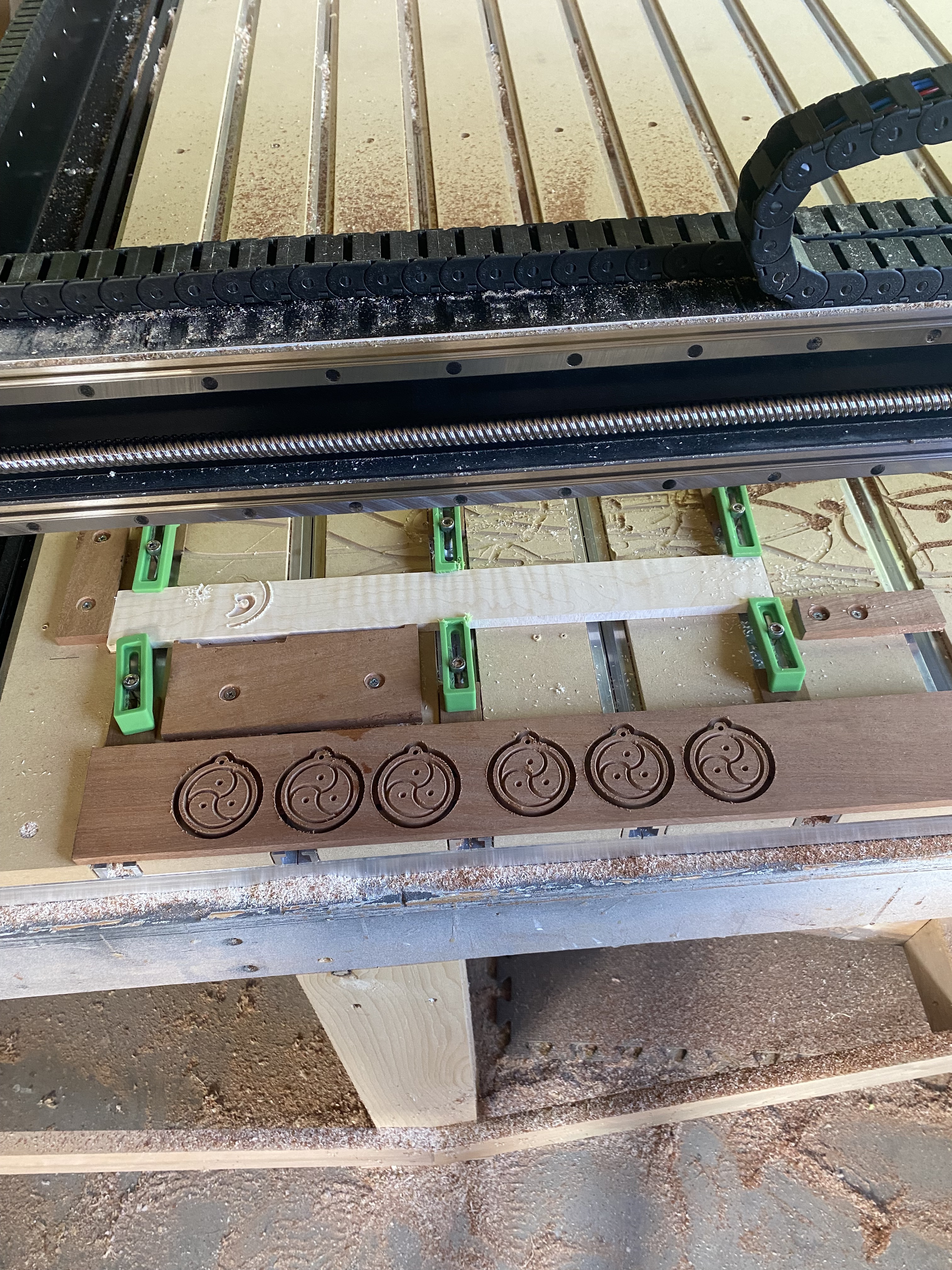
here are the 2 files the first one or the pocket side came out right ill post the pic of it done.
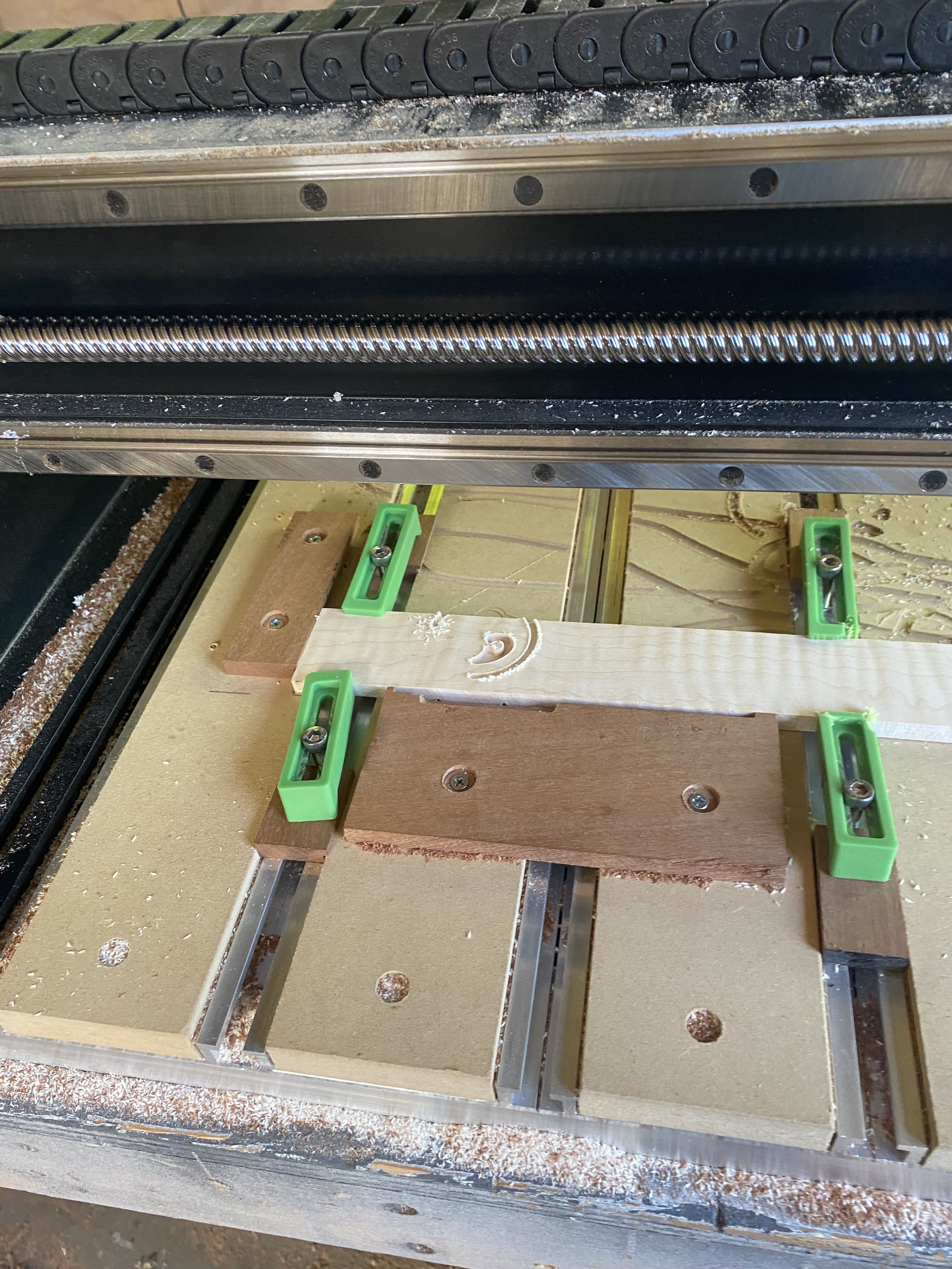
the second pic shows how i clamp and also the way the machine cut wrong on the piece still clamped.
I reset the X Y and Z to zero using (against recomendations from the forum) the bottom of my stock as my zero.
i followed the tutorial and used the paper feeler gauge to set z to the base of my machine.
im not sure how you mean to say how i handle my tool changes ?
the process seems same as when it works though. I turn on CM it tells me to put in the bit it wants first then it sets the height on bitsetter, then it has me turn on the router and then off to cut. if there is a tool change in the file then the machine stops and raises up and asks to shut off router then repeat the process to set the next bit.
yin yang pocket 45 degree x6.c2d (456 KB)
yin yang inlay 45 degree x6.c2d (80 KB)
Just looking at it the only thing I see is that the material height is not the same between the wood for the pocket and the wood for the plug. Seems like the plug material is to short for the plug. Maybe someone else sees something.
Seems you’re missing some steps, or didn’e describe it in enough detail…
1)Turn on CM & Initialize. It finds home position, then moves to tool change position & prompts for tool.
You load the 1st tool & Resume. It measures the tool & returns to the tool change position.
2) Move tool to zero point & set zero
3) Load file
4) Start program. It moves to the toolchange position & asks for a tool. You have the tool so you hit resume, and it measures the tool, again. Moves back to toolchange position. Turn on router & resume.
5) it cuts until it sees another toolchange, moves to toolchange position & prompts for router off & toolchange. etc…
Steps 2 & 3 should not be dependent, you could do them in either order. You just have to go back to the Run tab after the Jog tab to start the job if you do them in the other order.
Your inlay stock looks quite a bit narrower than your pocket stock. Yet in your design you have them both set to 2.75 height, and the vectors are about in the same spot.
Sorry guys I’m getting a bit spun. I was having a lot of problems with the inlays but at this point the machine is completely missing the wood on the top half of the cut can you see that in the picture of the light colored wood?
I made this exact file yesterday and have an awesome pendant that came out of the file but I only made one at a time
And today when I went to make six at a time by copying pasting in those same files, the first one came out fine and that’s the one on the darker wood and the second missed the wood on the top half of the cut.
Also, when measured with a caliper, those differences between the woods that you see in the Files shows the same on the calipers, they’re actually different by that much
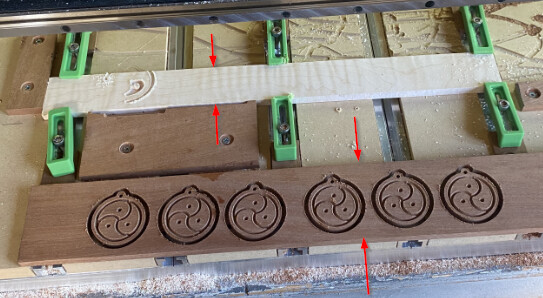
These 2 widths (Height in the CC file) are remarkably different. The lighter wood for the inlay would need to be about 2.1" to get the entire inlay on the wood.
2 Likes
In the first pic, with the darker wood below the clamped lighter wood, the darker wood has the pattern one way and the lighter wood has the inverse of that pattern. I am meaning that the design looks to be:
- flipped 180deg in either the X or Y axis, and
- it appears that the parts that are cut in the darker wood are left ‘raised’ in the lighter wood (i.e. a dot cut out in the bottom set is left raised while the surrounding is cut in the lighter wood).
Is this intentional? It is as if the lighter wood shows the cuts from the backside of a 3d ‘shell’ of the object…
Yes, the flip is intentional you have to mirror the image when you do an inlay because you flip it upside down
1 Like
I was going to suggest a scaling issue, and it kind of is. It’s just the wood was scaled down, not the model being scaled up…
Yes, the widths are notably different because I’m cutting the pendant and the image out of the darker wood ‘s and only the image on the inside out of the lighter wood
I believe the lighter wood on the inlay side of those two files should be 1 3/4 of an inch. I guess in width is what you would call it up and down in the picture though.