Setting up for a PGFUN touch probe

Unfortunately Carbide 3D support said they are “closed source” so they do not provide any information regarding their control board for the probe… their position is their board has “custom electronics” to work with their bitzero as a plug and play probe.

Which, fine… I guess that’s their position to take but they actually had a document online regarding the probe wiring before they updated their board and they’ve since removed it from their site. As I told their support - I will be better informed in the future when I decide to purchase from vendors. I’m not sure what they believe they benefit from by not publishing information on something like a probe interface but it is what it is.

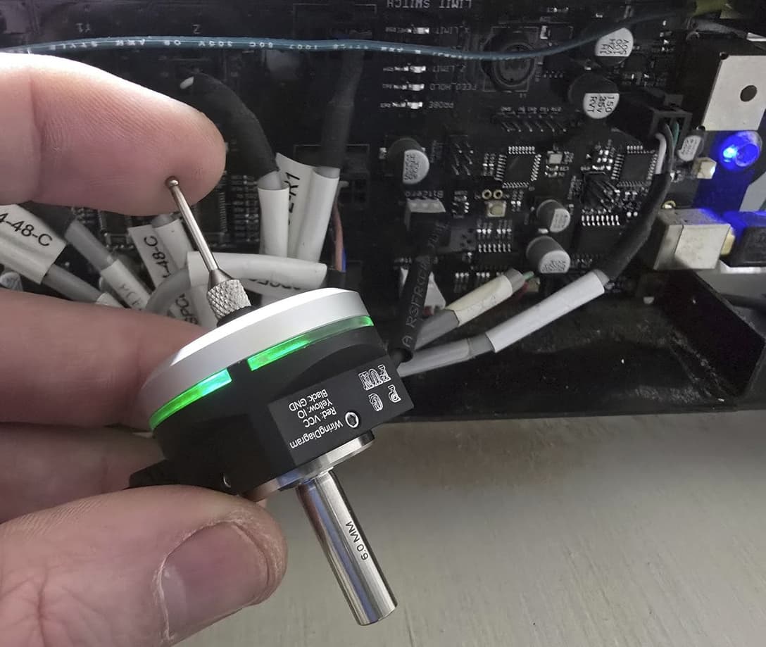
So let’s talk about what it does. I have a Pro XXL machine with the 3.0b revision control board. This board has a little 3 pin connector that is silkscreened “bitzero” and has 3 wires (red, black, white)

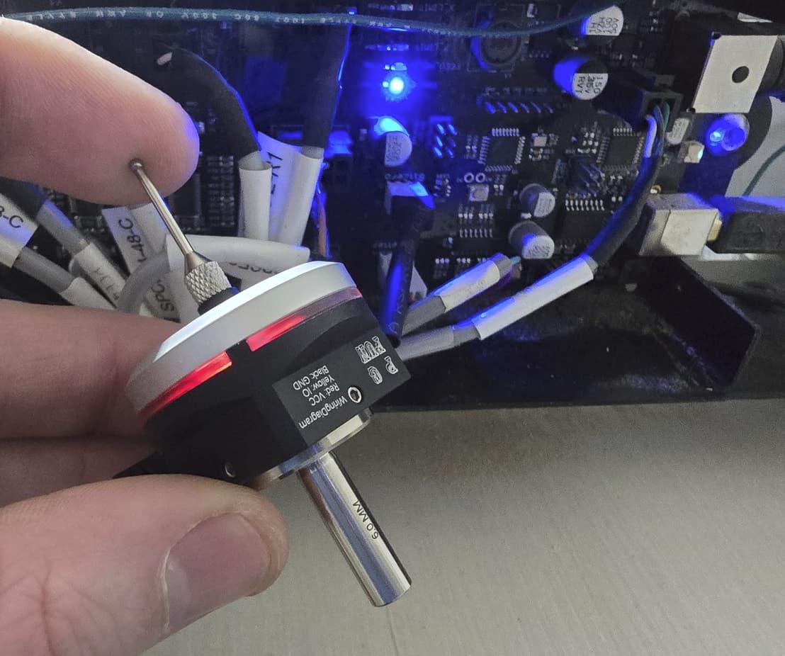
These wires correspond to +5v dcc, ground, and signal (low/high nominally open). So when the bitzero is triggered, it sends 5v over the signal wire which normally carries no current. That voltage change is what triggers the boards “probe” and on my board a small blue led illuminates.

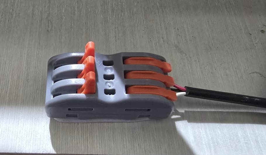
The first step for me, was to make their existing probe harness something that I can use for multiple probes. The PGFUN probe came with a locking 3 wire lever nut splicer. I added a little double sided tape to secure it, and spliced the probe wires into this. To allow me to quickly connect the different probes I purchased some 3 pin automotive wiring connectors. Here’s the basic setup for the connectors:

Lever nut splicer hooked to the probe harness wire coming from the board:

Quick connect female so I can swap probes:

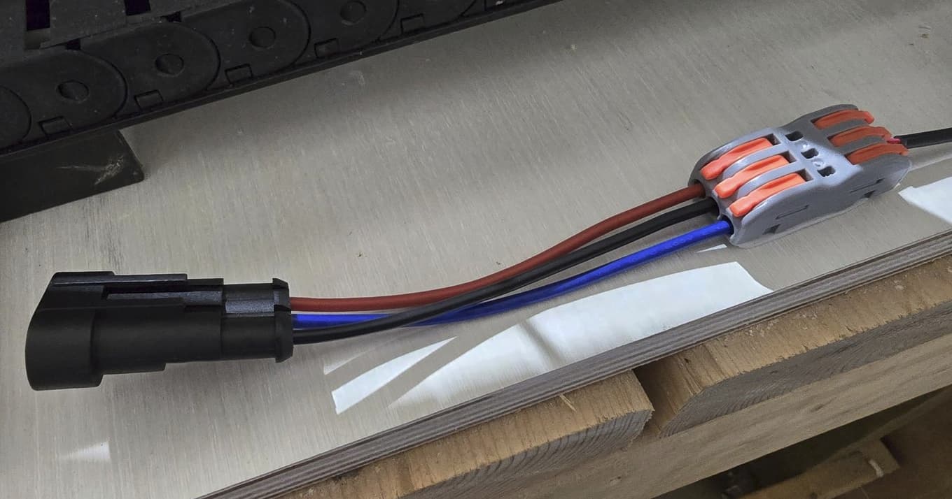
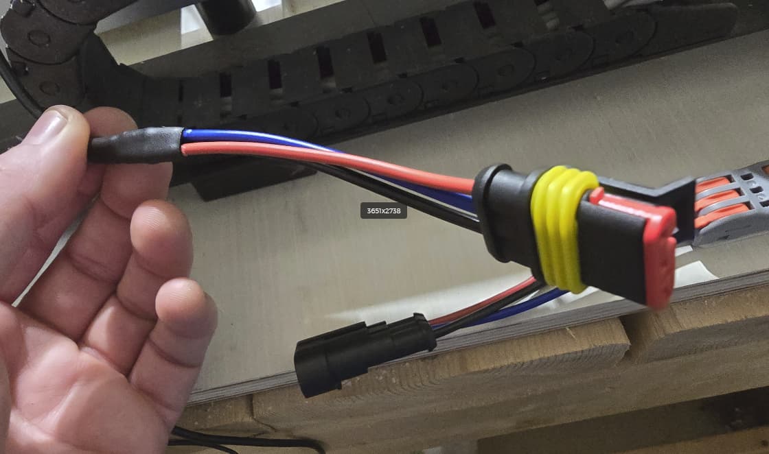
My bitzero cable with the male connector:

Now, the PGFUN touch probe is stated to run off 5-24v … I have not yet been able to power it using the 4.99 VDC coming from the control board. I have been able to power it using 12v dc. It’s also important to buy the right touch probe… they have two versions - a nominally open version and a nominally closed version. I actually bought the wrong one (the closed version) so instead of low/high, it’s high/low. I have the correct one coming.

If I cannot get the touch probe to operate off of the ~5v from the control board, I will power it separately with 12v. Because carbide would not disclose whether their probe circuit can handle current above 5v - rather than take a chance, I will install a 50 cent voltage regulator. This will take anywhere from 5 - 32v and output ~5v. I will wire that inline with the signal wire from the touch probe. That will give me some assurance that I won’t overload anything on the carbide controller board.

I will follow up with more details once I get the new probe in and finalize the wiring. I expect that if I can send 5v to the signal terminal on the carbide probe circuit that everything should work just fine.

1 Like

It sounds like you might be interested in some additional useful probe tools. I’ve had good luck with the electronics from topcom.cz
That links to their signal merger which lets you combine 4 signals into one output. Most notably it lets you easily invert signals:

Input channels can be configured to any combination of NPN/PNP and NO/NC input type.

Their magnetic connectors are also super convenient, though less valuable if you have the signal merger.

I’ve used mine to merge: bitzero, 3D Touch probe, and conductive/continuity probe(which proved to be much more accurate than the 3D Touch when used on conductive stock :slightly_smiling_face: )
Though I’m running a nomad and the circuit is just a little different.

In my opinion topcom electronics are well built and very fairly priced, ($35 for the 4 signal merger at the time of writing)
Definitely recommend checking them out for some interesting and relatively unique products.

This wasn’t sponsored, I just use their stuff and think it’s worth the time/money :beers:

1 Like

Thanks that’s very cool. I will keep in mind if I ever pick up a third probe. I’m pretty sure I am going to have to do something weird to get my touch probe going on 12v and regulate the signal to 5v. It would be nice if I could get it powered on the 5v that the board supplies but so far that’s been a no go. That control inversion is great… wish I’d seen that before buying a second probe… but I figured I will have a spare or use it on another project.

Oh and on the closed source topic, I can’t speak for C3D but I think there have been some past incidents which inform their current stance.

Personally, I don’t fault them for not being fully open but I do think it would be nice if they published a few specs on the more common/less bespoke subsystems. The probe circuit being a perfect example. Hopefully someday :crossed_fingers:

1 Like

Oooh your second probe can probably be converted to a conductive 3D Touch probe if you’re handy with a soldering iron. I think I ended up using very thin magnet wire for mine because:

  1. The thin strand will break easily if it’s caught on something (engineered failure point that’s easily replaceable and causes no damage :slightly_smiling_face:)
  2. Enameled magnet wire is fully coated so the insulation is excellent without being terribly bulky.

Pretty sure this is called flywire by some folks, often used for low level circuit board repairs.

Also fine to just keep on hand as you said, a spare doesn’t hurt, especially if you’re just learning…broken probe feels like an inevitability :sweat_smile:

If you’re looking to make it feel professional, I might recommend a tiny control box/electronics enclosure with a small din rail inside. A 5v meanwell din mounted power supply and whatever else you need in there would look great, stay protected, and be good exposure to a new system of dealing with electronics/controls.
(And I am just assuming the din rail stuff is new to most folks, as I haven’t come across it outside of industry in the Americas :sweat_smile:)

Regardless, lots of options and potential routes. Hopefully you get your situation figured out without too much fuss :slightly_smiling_face:

1 Like

Well I have some good news. The PGFUN touch probe does in fact operate off the voltage supplied by the C3D bitzero circuit (5v) and I was successfully able to power and test the nominally open version of the probe. So just a reminder, the nominally open probe sends 0 current on the signal wire until the probe is tripped, then it sends the current that is powering it, so +5v.

Here is the probe hooked up to the bitzero circuit (red wire = 5vdc, black wire = ground, white wire = signal/IO)

And when triggering the probe, note the blue led on the control board indicating probe:

So that’s a wrap, I have a fairly easy quick connect to switch between my bitzero probe and the touch probe, as C3D would put it “plug and play” … also they did at least silkscreen the basic info for the circuit on the board, I hadn’t noticed that previously. But we’ll never know if the probe circuit can handle more than 5v on the IO wire… but we don’t need to worry with this touch probe since it can’t send more than it’s receiving.

Hope this helps someone in the future.

3 Likes

This topic was automatically closed after 30 days. New replies are no longer allowed.