Still kind of new at this. I have a 24” round that I want to put a sports logo on for a table top. How do I set zero?
Usually with circle shapes you use the center as zero.
1 Like
If you have a good quality Center Finder or similar head for a rule the center is easily marked.
If I have an absolutely critical placement, I secure a sacrificial piece of MDF and then cut a slightly larger pocket than the stock and then bolt it down in the center.
1 Like
There are several mathematical ways to get at the center of a circle. Google that and you will see them.
One using “chords” is basically what I think the BitZero uses.
As @WillAdams suggested use a square with the v shaped head.
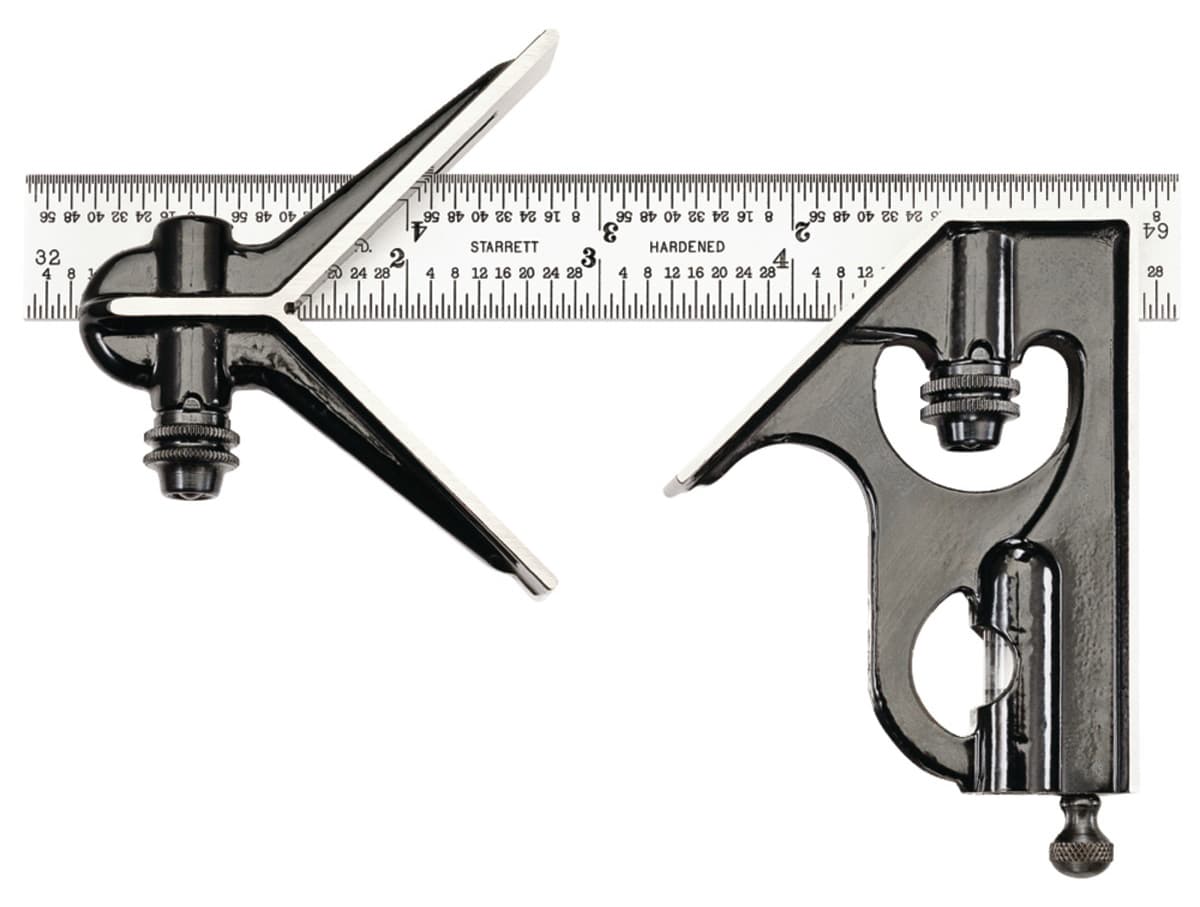
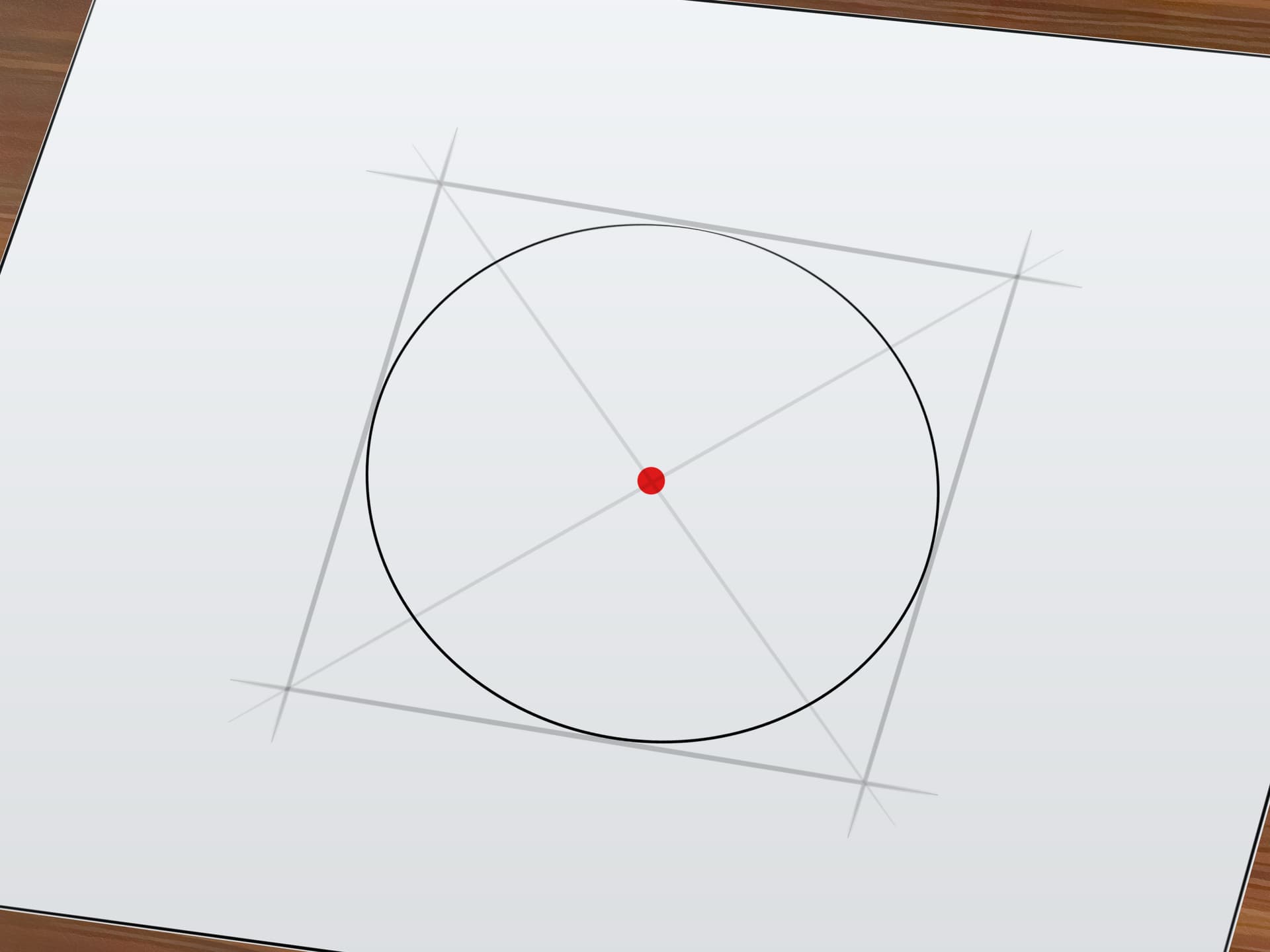
If you have perfect circle then put the square about 90degrees apart and mark with a pencil and make an X.
If you don have a square with the v head then draw a square the same dimension as the diameter of our circle. Draw a line from opposite corners and overlay the paper on your circle and punch through the paper with somthing sharp.
2 Likes
I just found a copy of Starrett’s 1980 100th anniversary catalog on the shelf up here in the engineering department. It pointed out that Mr. Starrett invented the combination square in 1877 and it was his company’s first product.
1 Like
The older advertisements for the combination square were a hoot. They have a bit more at:
https://www.starrett.com/news-events/frequently-asked-questions-on-the-starrett-combination-square
I will also note that their patent game was so strong, Stanley instead marketed their “Odd Jobs #1”:
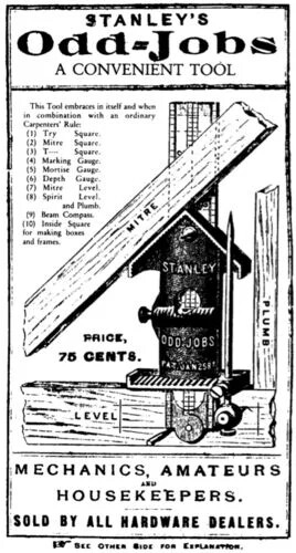
though it continued long after the patent ran out, not disappearing until 1936 or so.
(I couldn’t resist getting one of the Rockler reproductions)
1 Like
I made a bottle opener out of a hockey puck. I printed an L bracket that was 30 x 30 mm square and 60 mm long. I used a “cubetruss_corner” module from the BOSL2 library in OpenSCAD and printed an L bracket with my 3d printer. It used much less filament than a solid L block and was quite strong.
With my calipers, this wound up being 30.1mm thick. I put the BitZero on the corner of the truss and used blue tape / CA glue to mount the hockey puck. I had to take the Z height of the puck itself and move the spindle manually 30.1 mm in the X and the Y direction, which gave me the coordinate of the near left corner of the cube/square circumscribing the hockey puck. I had the stock set to a square in my software.
Hope that makes sense! Without a printer, one could make his own jig with wood and the Shapeoko for the BitZero.
include <BOSL2/std.scad>
include <BOSL2/cubetruss.scad>

width = 30;

translate([0, 0, width/2])
cubetruss_corner(extents=[2, 2, 0, 0, 0], strut=2, size=width, clipthick=0);
1 Like
I just use a ruler or tape measure & mark the center in several different directions.
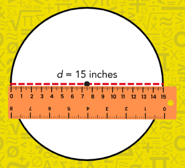
It’s close enough the design looks visually centered, even if it is off by a tiny bit.
1 Like
This topic was automatically closed after 30 days. New replies are no longer allowed.