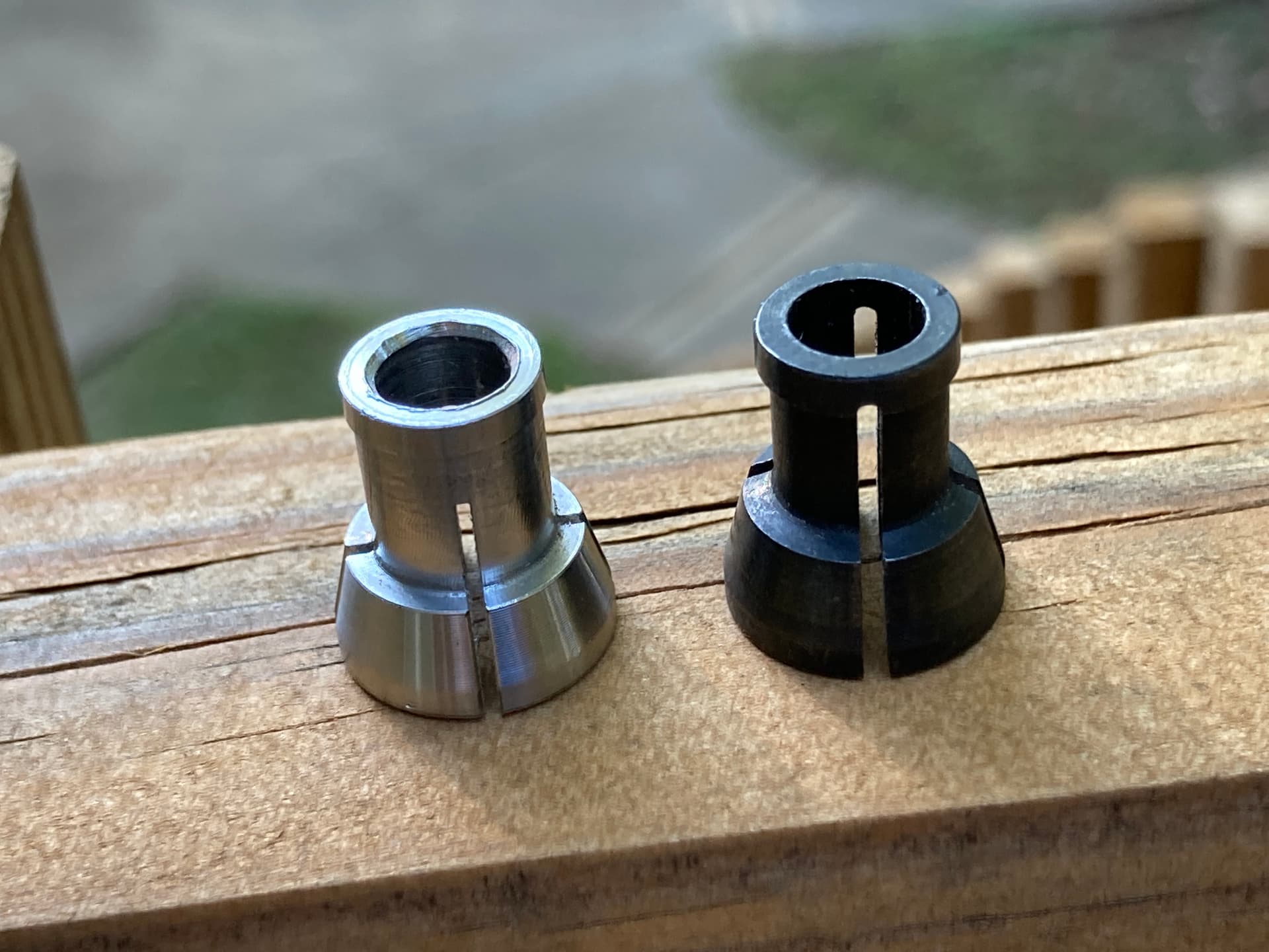
That noise is chatter, which can appear in a variety of situations but mostly it means the endmill is vibrating around its normal axis position. This is bad as you then get sudden variations in tool engagement in the material (which can further feed the chatter). As other have noted, here it’s probably due to a combination of (too) aggressive depth of cut and the shank rubbing on the wood, maybe combined with a semi-loose collet.
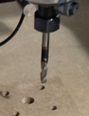
Indeed a ballnose should preferably not be used for roughing, it’s best used for finishing curves when there is little material left to remove.
Finally, chatter develops more easily when you use a large stickout (i.e. the length of the endmill that is outside the collet), the longer the stickout the more the endmill can deflect, and when the tool deflects it wants to come back to its rest position, then it will deflect again, and you get a periodic “bouncing” of the endmill to/away from the material…chatter.
Yes. Even though you may get away with using endmills with shorter length of cut, the straightforward solution is really to buy endmills with a length of cut that cover your deepest toolpath Z range.
If you can’t find them, then you need to design the CAM such that you will minimize or avoid the rubbing but that’s not always possible. In your specific case here, you could have chosen to do the bottom side roughing by starting from the outside of the stock, and having the toolpath remove all material from the outside in, layer by layer. This way the tool shank would never rub. However, you would loose the two location pins too, so you would need to adapt your workholding strategy. As I said, it’s just much easier to get a tool with longer LOC 
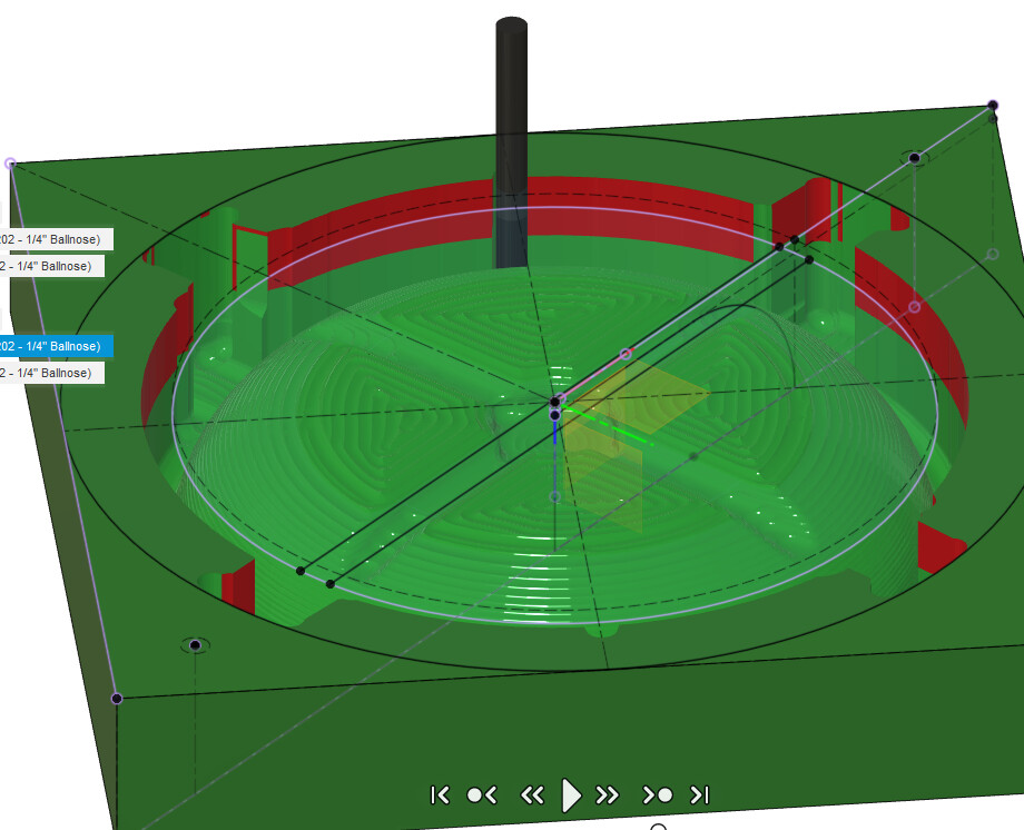
That’s just the Simulation feature in Fusion360 (select one of several toolpaths, then click on:

To recap:
- use a straight endmill for roughing instead. It will leave “steps”, but the finishing toolpath with the ballnose will take care of that.
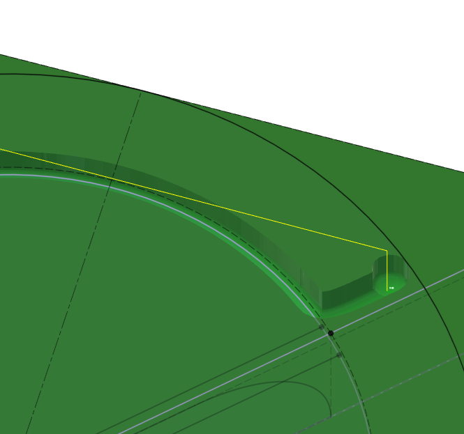
- Your “max roughing stepdown” is 0.39", which is can be fine when using specific entry strategies and low width of cut (“optimal load” in Fusio360 lingo), but you used a 0.1" optimal load (2.54mm), and even though you did specify a “helix” entry into the material, the toolpath starts with a straight plunge, 0.4" down. I have not tracked down why it doesn’t, but that the way it is set you end with 0.4" deep slotting, with a ballnose endmill…which is way too aggressive
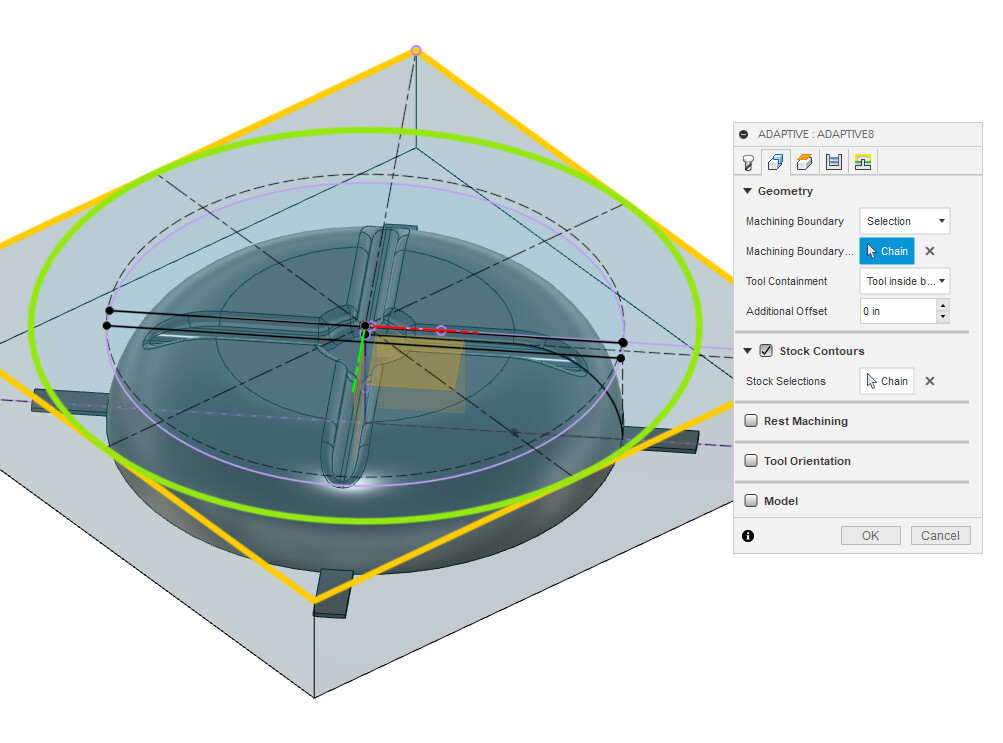
If you edit your toolpath to declare “stock contours” and use the square outline of your stock:
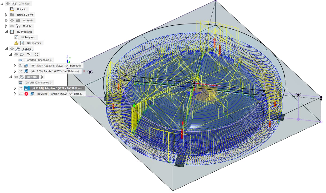
using the same cutting parameters you get this:
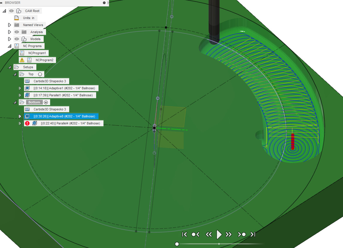
which at first looks somewhat similar, except this time it will enforce the helix entry, and the optimal load you set, taking large circular bytes:
Of course now the cutting time has increased (30min versus 12min initially), but I think it would make for a more uneventful cut. It’s still using your ballnose endmill in that simulation, but again a square endmill will mean less trouble for roughing