Get a good quality level, assemble the frame, then use the leveling feet to establish level.
Well flat and level are two different things.
If you know your table isn’t flat, you can still get it mostly level.
Once you setup the router on that surface, those aluminum tables are going to get the assembled unit mostly flat. Sitting on a mostly level surface, you might find a couple of places where you have to add feed or shims to keep the unit from rocking.
Then move onto checking the indicator to table distance.
That is how I’d proceed.
Perhaps I’m putting the cart in front of the horse.
Let’s forget about leveling the table and the aluminum plates.
Build the entire gantry, mount the router, attach a dial indicator to the router.
Without changing the axis of the dial indicator, fixed position:
-
Move the dial indicator/gantry to the Front Right corner, zero the dial indicator.
-
Move the dial indicator/gantry to Front Left corner, record the reading.
-
Move the dial indicator/gantry to Rear Left corner, record the reading.
-
Move the dial indicator/gantry to Rear Right corner, record the reading.
-
Adjust the leveling feet to zero out the error, repeat above steps till all four corners are equal.
-
Move the dial/indicator and scan the plates for TIR (Total Indicate Readings), shim low spot(s) as applicable.
-
Verify ALL readings for FLATNESS.
Perhaps LEVELING the plates initially is to “rough-up” or a coarse adjustment and to keep the gantry referenced to gravity.
I’d trust the aluminum plates are fairly flat. I’d assemble the gantry and plates and shim the assembled unit so it doesn’t rock on your table (or use leveling feet or whatever).
Then I’d start measuring gantry to table and add shims between the frame and the table to get that as consistent as possible.
I will say you can develop analysis paralysis at this point. Sometimes doing it one way will clue you in on a slightly different approach. The thing will come apart by removing the screws, nothing permanent.
So I say put it together any way you can and then start poking at it, you might learn you need to make adjustments where you simply aren’t expecting.
1 Like
One old fashion way is with winding sticks. There are many tutorials on YouTube. Tou get the base coplanner then level. Just remember the +/- tolorance of the machine and good enough can be achieved where as perfect is not attainable because of a moving Target of the +/- tolorence of repeatability. Many people over think simple problems. Just do the basics in steps. Make one change and measure. If you make multiple changes and it does not work you don’t know which change did not work. KISS keep it simple stupid and it will work.
2 Likes
Plate Tolerance +/- 0.005" TIR.
Pressing on with the build.
My objective is to level the plate best I can with the leveling feet. Since I don’t have a machinist level or precision level nor a flat level table, I am going to adjust the feet as follows:
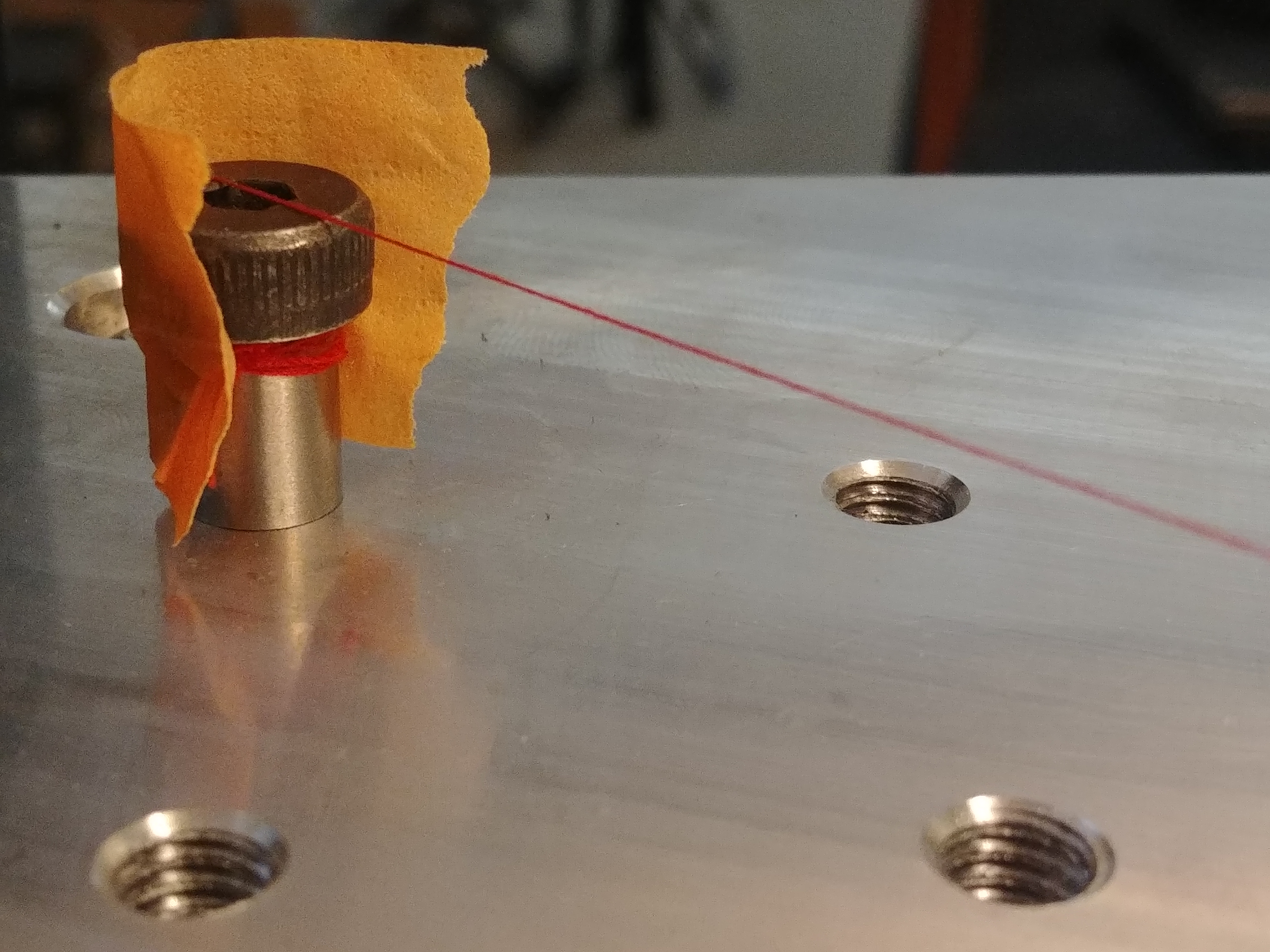
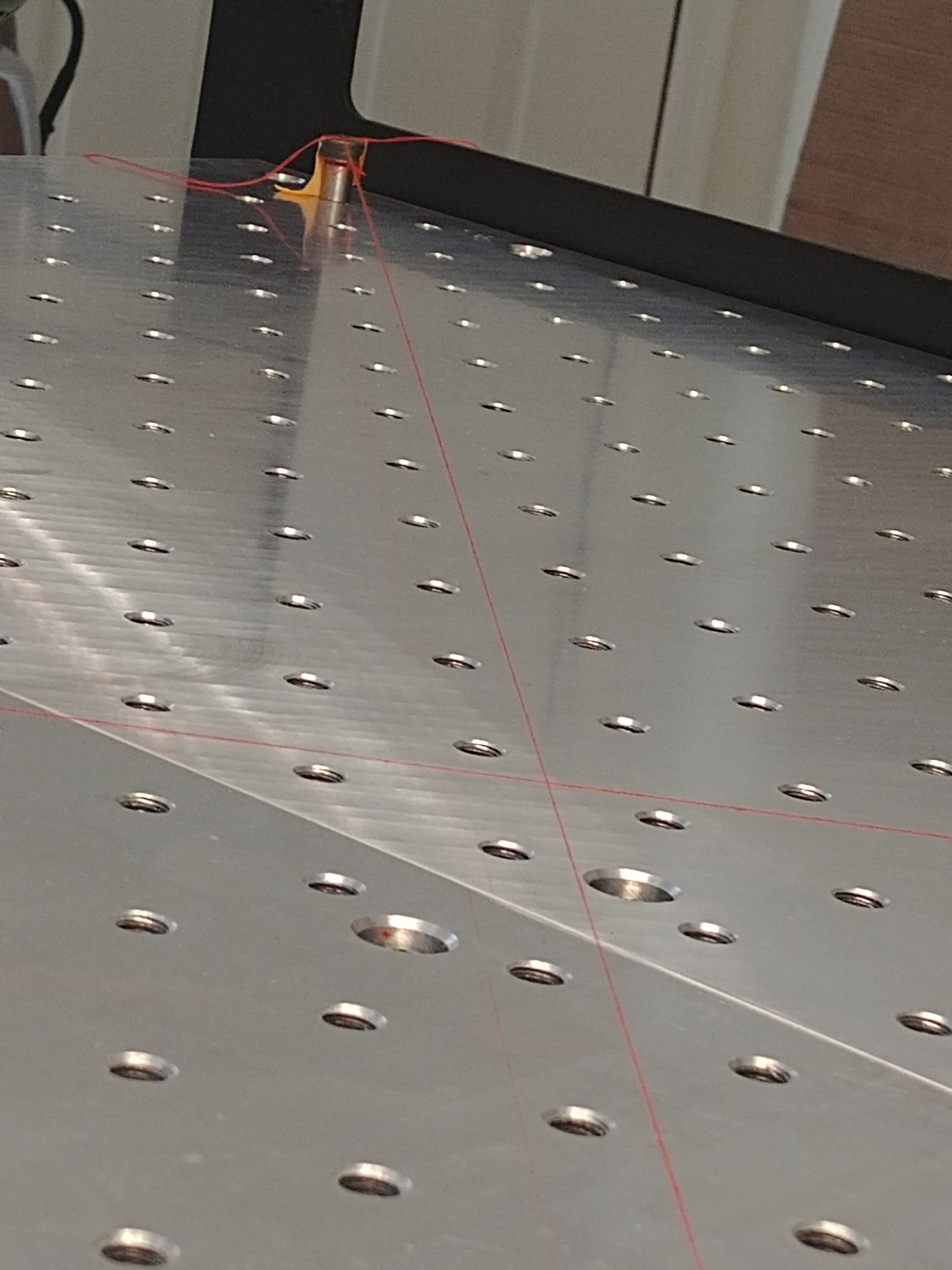
I will installed 4 shoulder bolts in each corner of the aluminum plates, verified that all 4 shoulder bolts are of equal height from the top of the plate.
Run a thread/string from the top of each shoulder bolt diagonally. One set will of the diagonally running thread/string will be elevated to the thickness of the thread/string.
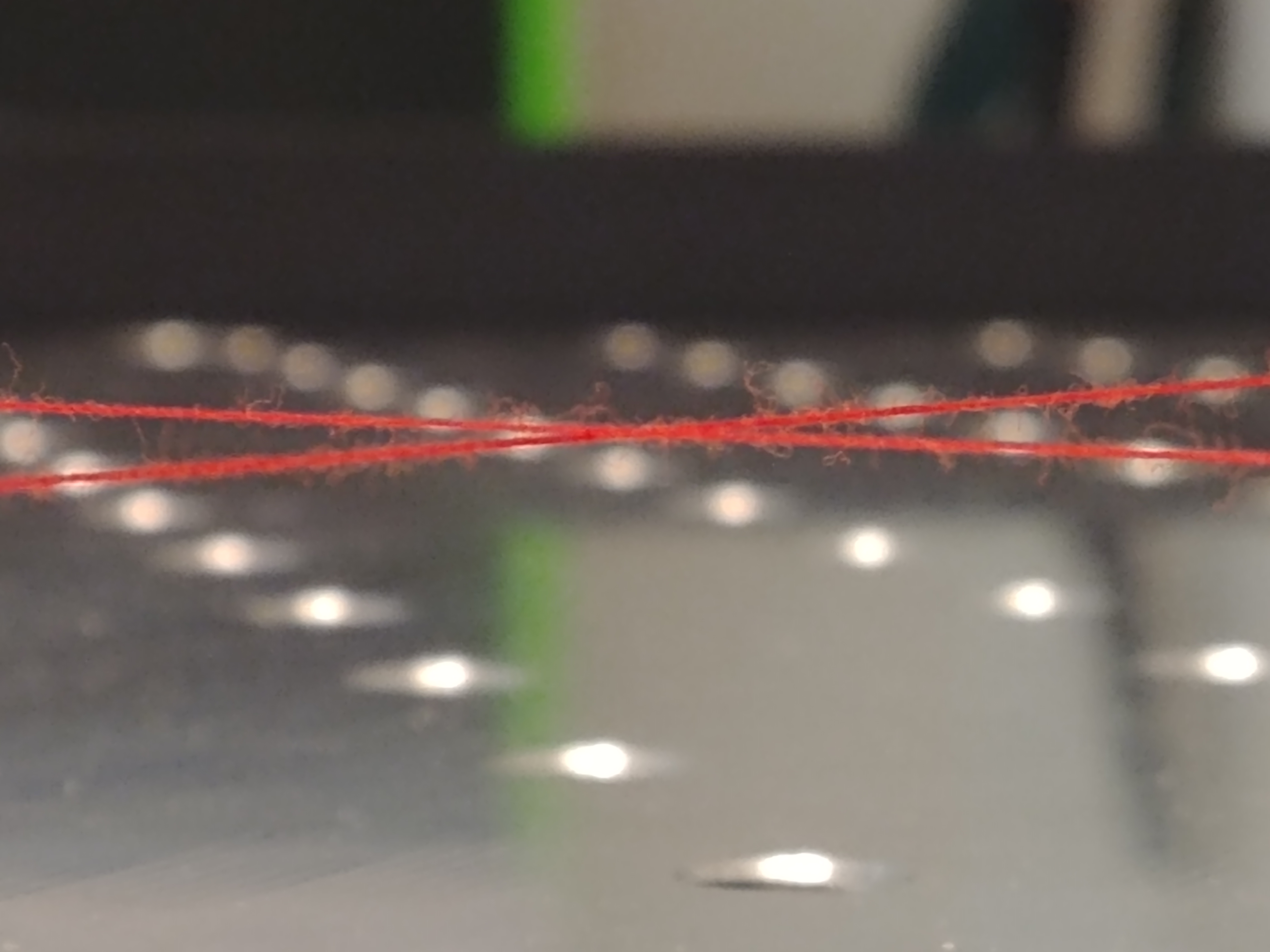
Adjust applicable leveling feet till the intersecting sections of the thread/string touches. Ok see when the thread/string touches, I am going to use the aid of my mobile phone’s macro camera. My tired old eyes aren’t what they used to be.
1 Like
Running into more issues … Got to the end of the instructions … Squaring … and bumpy axis.
I move the gantry forward and both X axis touches the Left Y and Right Y frames. Moved the gantry back and the X axis touches the right Y frame. Whereas the left Y frame has is 3/64" gap.
The problem about moving the gantry with the belt on is that it requires some effort. Also, no matter what I do to eliminate the bumpy feeling along the travel of the Y axis by adjusting the eccentric nut I can still feel and hear the bump.
Here’s where I went wrong, I should have loosen the eccentric nuts such that there was no tension on the guide pulleys during the installation on the Y, X & Z frames. In my opinion, the online instructions should have stated this. I think the bumpy feeling is the applied pressure on the inner bearing race walls. This exertion of force caused the bearings or bearing walls to become what is known as a notchy bearing.
Removing the belt from the motor pulley will result in a smoother feel of the moving assembly.
No matter how I shift the frames to square off the X axis to the Y axis I still have a gap. I can split the difference from the front and rear and call it good. Not sure how to adjust the frame so that both front and rear touches at the same time. As it is the left Y front is 0.027" gap and the left Y rear is 0.022" gap.
Need your thoughts.
I have concluded that the bearings on the guide pulleys are damaged due to too much preload during the initial assembly and need to be replaced.
The 3/64" inch gap is good enough I think, unless I am missing something, maybe clamping the frame to pull the left Y closer.
Is the x motor connected to the controller when you’re moving it by hand?
If so, you’re generating enough electricity by rotating the motor to power the stepper driver which immediately tries to hold position. As soon as it holds, you’re not generating enough voltage and it powers down. It’ll feel like thunks as you move along an axis. Not a mechanical issue.
1 Like
Everything wired up … I did not about that, a generator. I have the belt removed making it easier to move the gantry. I still got that bump feeling/bump noise. Found the bearings have been compromised during the initial install. The guide pulleys were preadjusted at the factory and the tension was excessive. By moving the gantry during squaring, I damaged the guide pulley bearings. Lesson learned for new comers, don’t install any of the rails without adjusting the guide pulley eccentric nuts to the widest position. This adjustment can be performed once the rail assembly is on tbe rails.
This topic was automatically closed 30 days after the last reply. New replies are no longer allowed.