Any user upgraded from the MDF base plate to a 1/2" aluminum plate? I am trying to level the 2 Aluminum halves but finding out that perhaps the 3 flat bottom interlocking plates are not strong enough for these 1/2" aluminum plates.
Your thoughts …
Any user upgraded from the MDF base plate to a 1/2" aluminum plate? I am trying to level the 2 Aluminum halves but finding out that perhaps the 3 flat bottom interlocking plates are not strong enough for these 1/2" aluminum plates.
Your thoughts …
I have done it, didn’t have any problems. Describe the issue you’re having for us.
Re Edited … Found my issues … Damaged straight edge… 2 am oversight.
Lol, I cannot even begin to tell you the 2am hysteria that I’ve managed to create for myself.
Glad you found your answer.
I don’t have an XXL, but when I setup my aluminum tables on my standard size, I mounted an indicator on the carriage, locked the carriage, and used that as my reference. I placed shims between the table and the frame to get my table within just a few thousandths throughout the entire range of my spindle.
It didn’t take long and was worth the effort.
Before I did that, I switched out half the button head screws that hole the extrusions, to flat-head. This guarantees that my extrusions won’t move relative to the steel supports, because the flat-head screws are wedged into them.
Have fun and make something and post-back, love seeing project posts.
Phil here’s my orginal post before I edited.
Hi Phil, so I followed the Carbide online assembly instructions, base frame assembly up to the end.
Before I proceeded to the carriages steps I decided to tighten all the screws to check if the 2 plate halves were coplanary using a straight edge on top of both plate halves.
I could rock the straight edge from one half of the plate to the other half. This concluded that the center half where the 2 plates butt up was high.
The only deviation from the instructions was tgat I did not level the table, did not level the legs, and did not square the base frame for the carriages alignment.
Reason I omitted these 3 critical steps was that I wanted to see if the 2 plate halves will be coplanar and also if the base frames will carry the added weight of the aluminum plates and maintain its rigidity and stiffness.
My second reason was that this XXL is huge and its assembly area is a temporary location, therefore moving the XXL will require that it be orientated during the moving process to fit through a standard door opening.
Hence, if leveling the feet will correct for the coplanar issues than instaling the carriages will add extra support/stiffness to the overall base frame assembly.
However, I did raise one end and that did not change the high middle spot of the 2 adjoining halves.
I have concluded (theoretically) that the best way to assemble the base frame is to perform the assembly upside down having both plate halves elevated on a known flat datum. This will establish a flat reference for the plate halves, then add shims to the 3 crossmember support where needed as well as the front and back frames.
.
Also to note … NOT to use the side edge as a visual reference. But to establish a reference using the bore holes.
Reason being is that the plate halves are mirror imaged when assembling. Any errors during the manufacturing process will be seen along the sides since the plate halves are orientated facing each other (mirror image).
Interesting.
My method when swapping to the aluminum was to snug each of them down firm to the base, then measure with my indicator. I got a good idea of where adjustments were needed and then used paper/cardstock as shims and in short order had everything pretty darn flat.
Whether the tables were coplanar or perfectly flat was less interesting to me than the indicator-measured distance.
Phil, I decided to scrap my thought process in making the aluminum plates coplanar to each other. Because of additional materials it was not cost-effective to go this route. I will do it like you did after I assemble the entire unit.
I still can’t get over this thought that the frame and cross braces is not structurally solid to support the weight of the aluminum plates.
I inverted the assembly to see if I can add C-channels or I-beams.
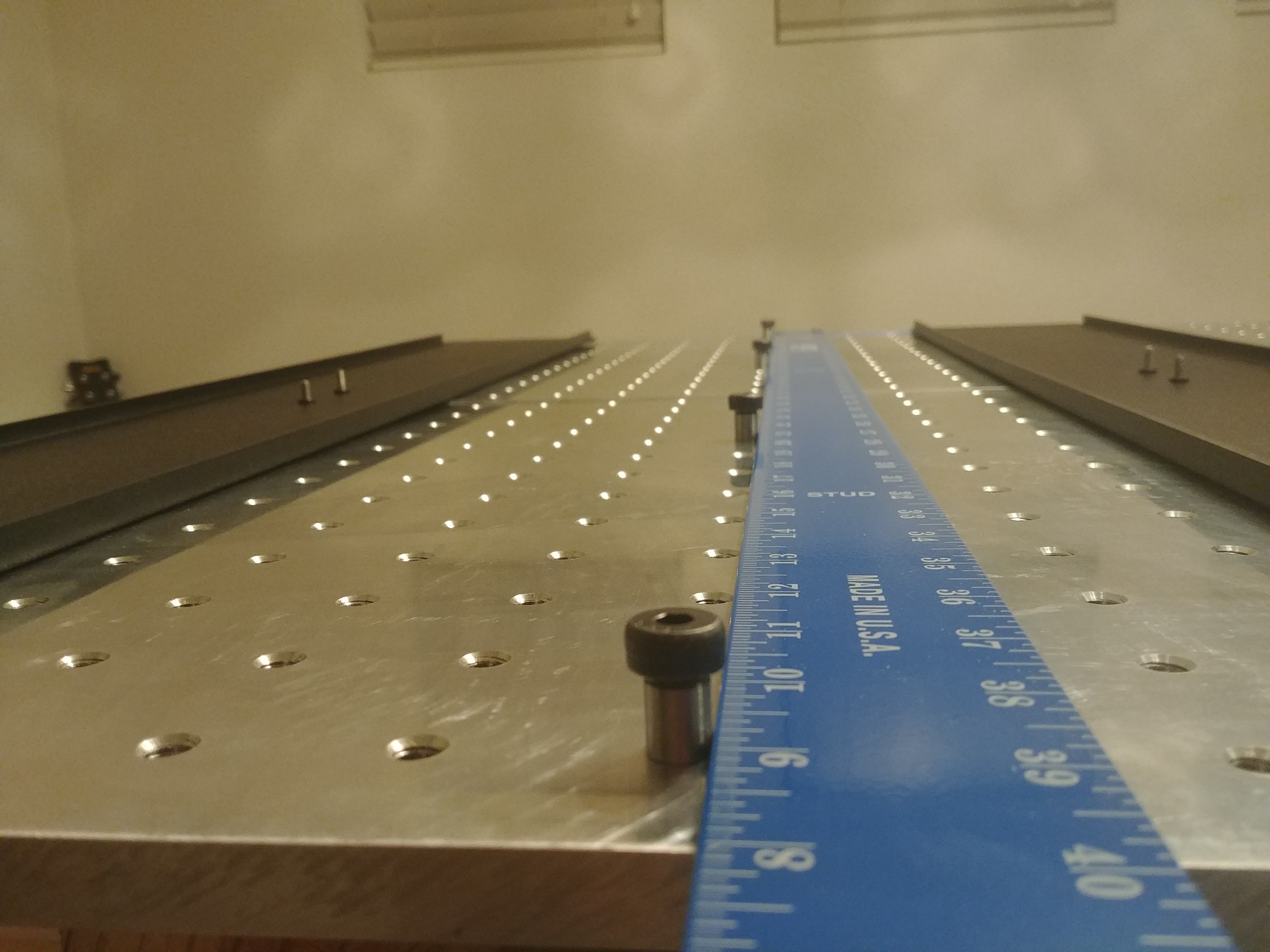
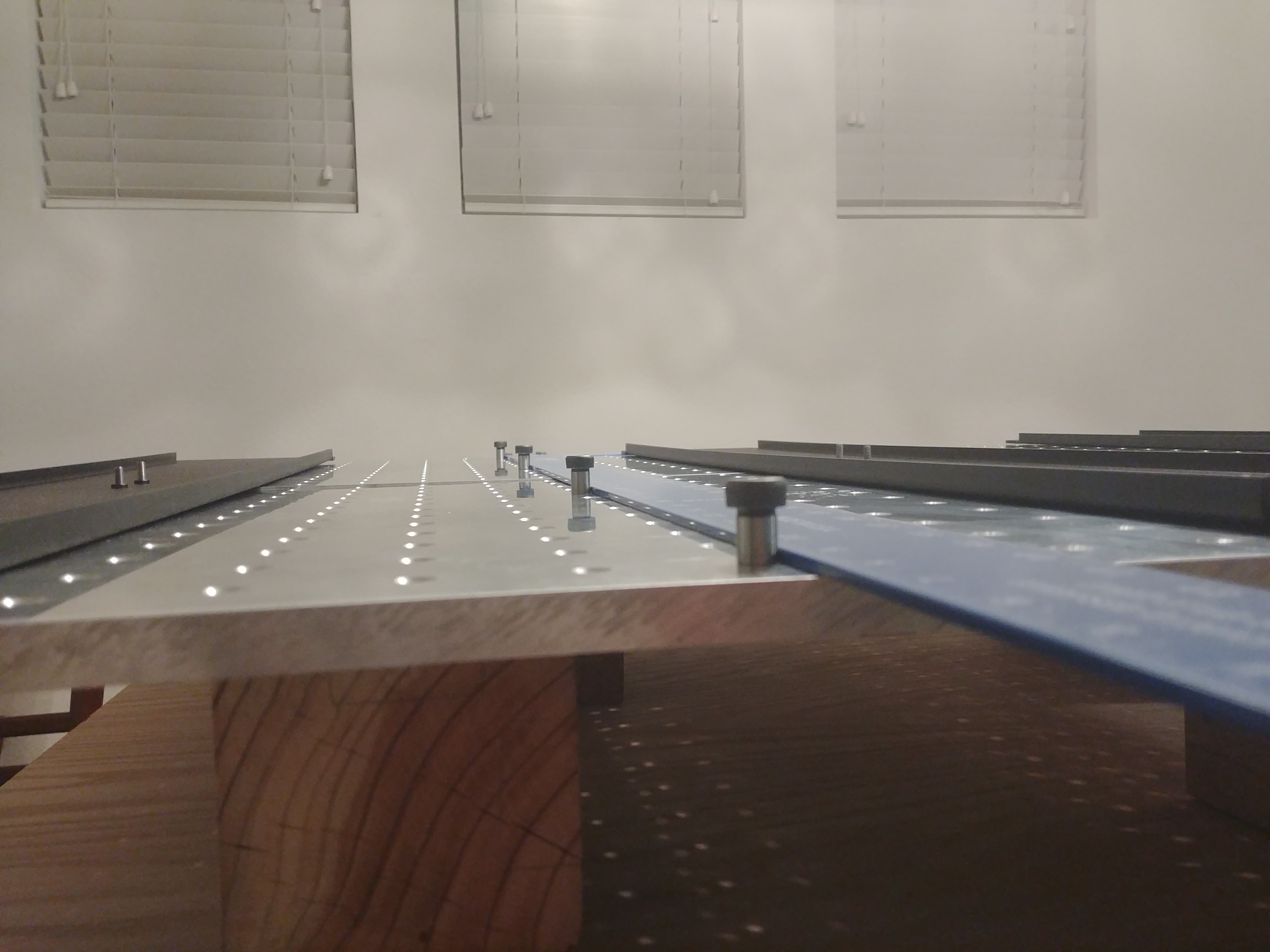
Also I am using a shoulder bolt in the threaded holes and a straight edge ruler to align the 2 aluminum plates. This is a go-nogo so accuracy of the straight edge and shoulder bolts are not factored in. I was able to shift the plates to make the alignment using 1 of the cross member brace as a pivot point. This was done with just the center bolts in place as the pivot point.
I wish I had two parrallel bars that the aluminum plates can rest on so I can establish an initial reference plane (coplanar).
Not sure what I’m seeing in the picture.
In my case, the seam where the two plates “join” it probably a little tight towards one end. I wanted to make certain my screw spacing was consistent over the seam, so I cut 2x2 hole patterns in two blocks of of 3/4" wood, added countersinks using a piloted bit, and screwed them into the plates to make sure the holes were aligned properly. I did that AFTER I had the plates adjusted via my indicator.
On the flatness thing, I was less concerned about the plates being a reference flat surface and more concerned with them measuring a consistent distance via my indicator, BECAUSE the gantry itself is the true reference.
Imagine a gantry with a .01" dip in the middle (I’m being extreme). A perfectly flat table will result in everything you machine having a contour reflective of the sag.
Also in my instance as I said b4, I was dealing with the original smaller machine. I wouldn’t doubt there could be some sag in 1/2" aluminum over a span 2x that of my machine. BUT, I would simply shim between the center of the plates and my support table, to make certain my indicator wasn’t showing a dip.
You can see the 2 aluminum plate halves in this pix.
I will take your advise and use a dial indicator to get the TIR then shim the low spot. My only concern is that the center brace was not designed to support the weight of the aluminum plate thus adding shim will be a temporary fix.
I am thinking about adding additional support as in 4 each C-channel iron running parallel to the 3 existing black cross member support bracket. The reason for 4 is to place 2 C-channels along side the center cross member. Mainly for aesthetic.
Then add 2 additional C-channels running perpendicular. The 4 C-channels will rest on the 2 C-channels running perpendicular.
I will then relocate the adjusting feet to these 2 perpendicular C-channels.
This C-channel additions will carry the load of the aluminum plates. My only concern is that this will raise the entire platform by approximately 4 inches. I am not sure what effect (Center of Gravity) will this 4 inch elevated height have on the CNC.
I think I’m over thinking this whole thing or just complicating matters by adding extra support which can be done minimally. Hey that’s why I am posting my thoughts to find a better solution.
I need to build this CNC then relocate it to the garage. But to get it through the door, I have to carry the CNC flipped side ways. With the heavy aluminium plates, I can see the frame twisting if I lift one side/end. Hence my reasonning to add supports.
Agree with everything you say.
I’d suggest getting the initial setup done, then run the indicator to the center of the table and push on the table with your thumb, and see what kind of deflection you see.
After you know that value, you can decide how crazy to go.
Just to add that in my case, I was dealing with shorter spans. But I didn’t feel like the braces were needed for support as much as simply alignment.
As I agreed to earlier, you might be in a different ballgame because your length is 2x.
Phil, are you the inventor of the Thien baffle design?
I will take you up on that … Press on and see what the dial indicator is reading.
Thanks for your thoughts and suggestions. Many times I get bombarded by over thinking thus slowing progress and complicating the matter.
Yes. I guess I need twenty characters.
You and I were cut from the same cloth.
I can really work myself into a frenzy sometimes.
I have trained professionals that talk me off ledges.
Well Sir, its a pleasure chatting here with you and knowing you are one of the greatest contributor to the DIY commuties.
Oh pfft. We all stand on the shoulders of giants.
I’m stump … So I flipped the frame back right side up.
How does one establish a datum given the torsion box I built isn’t flat?
The instructions states to level the table … Done … Only this torsion table (TT) top has an unlevel area … The level rocks so obviously the TT is not flat.
After the TT is level, adjust the CNC feet for a level condition. I can adjust the leveling feet to max height thus creating a level condition. I am sure this is an issue as all this adjusting is twisting the CNC platform.
I wish I had a surface plate, then I know I have a reference point to start.
Stump …
If I press on and build the gantry and mount a dial indicator, scan (TIR) the entire aluminum plate is the low spot corrected by shimming that part of the plate OR adjustment the leveling feet.
Not sure if I’m making sense but without a known flat reference how can I proceed with the build?