I originally was trying to order the Shapeoko Pro around the time when C3D was having issues sourcing linear rails, and then the 4 came out and I ordered an XXL the day it hit the store. I figured I was going to be in the occasional use category, but I’ve found I use the machine all the time. As I learned more about CNCs and how they are built I started becoming quite jealous of Pro owners and their shiny rails! After learning how to mill aluminum I did notice quite visible movement caused by the x-axis v-wheels flexing under the load. This dancing around caused inaccuracies in my parts and broken bits from fast dulling. Obviously the solution is to run conservative feeds and speeds, but sometimes the flex was unpredictable.
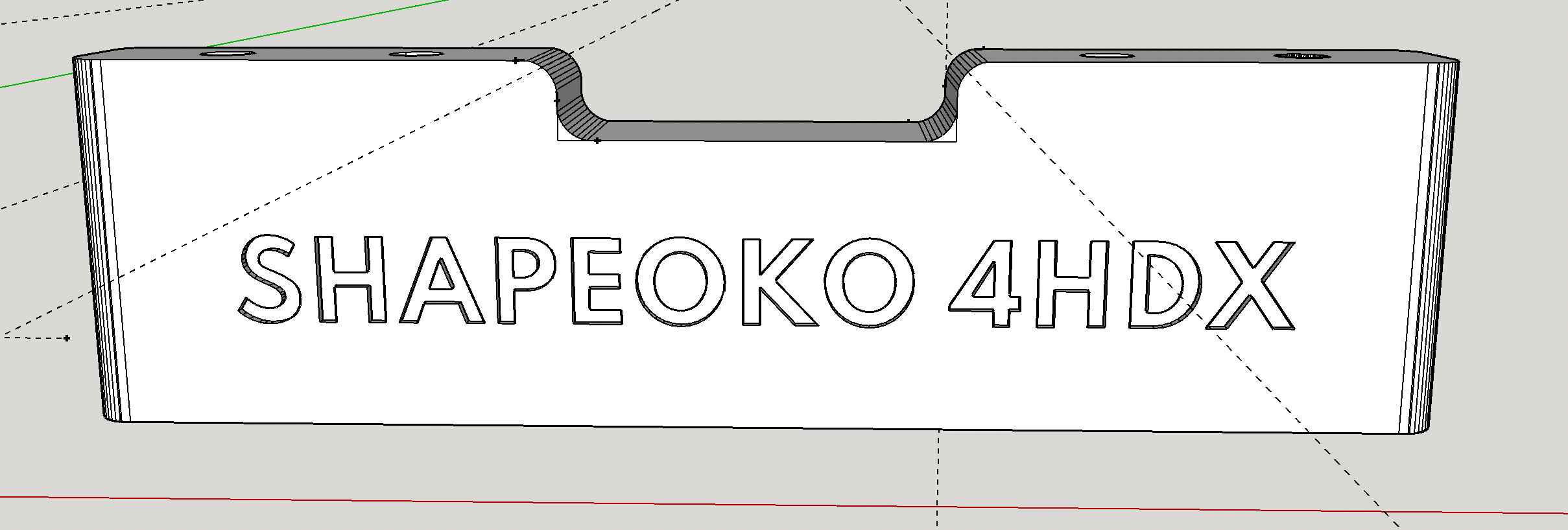
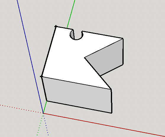
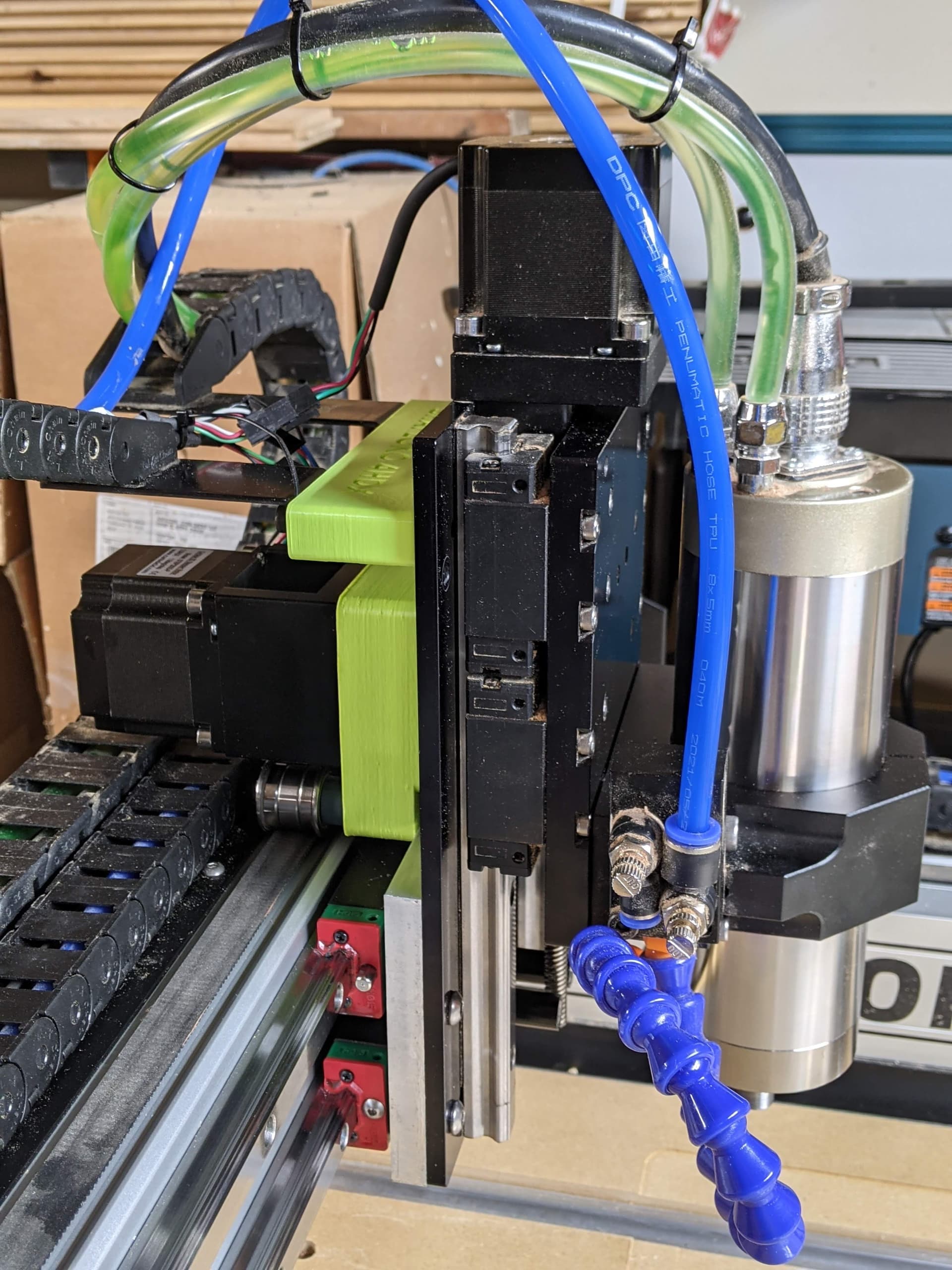
Since the 4 is effectively a v-wheeled Pro, I’ve designed my upgrade to use the Pro as a template, and also using the the existing holes in the Z-Plus that are used for the Pro since it doesn’t use a carrier plate. On the 4 the carrier plate mounts the drag chain tabs, stepper motor, pulleys etc, and where as on the pro all of these things mount directly to the Z-Plus. C3D did some smart optimizations like this when they designed the 4. This way there is only one part for the Z-Plus or HDZ that work on both machines. Of course I didn’t know all this until I watched videos again on repeat for shots of specific elements, and pouring through the docs for both machines.
Additionally I took some hints from the design the PrintNC, and have used 3d printing extensively to design alignment jigs and adapters. I selected 15mm linear rails from Amazon that were about $50 each. I made several different versions of the jigs for different stages of the rail installation. Here is the first type:
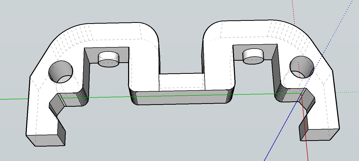
It snaps very securely into the v-rails with no play, and also roughly aligns the holes of the rails together.
The second don’t snap on as securely so they can be moved all over the rail for alignment of each screw.

The third type were a burly version of the first without the alignment pins. I found they were not really necessary and the second type would work.
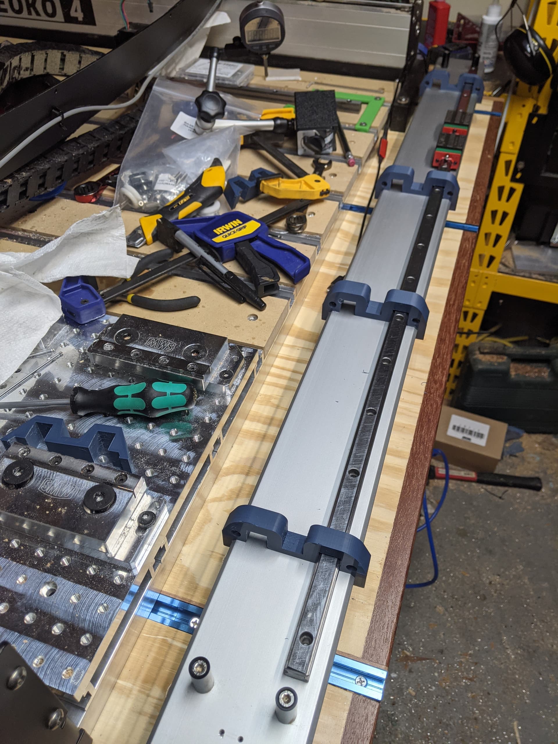
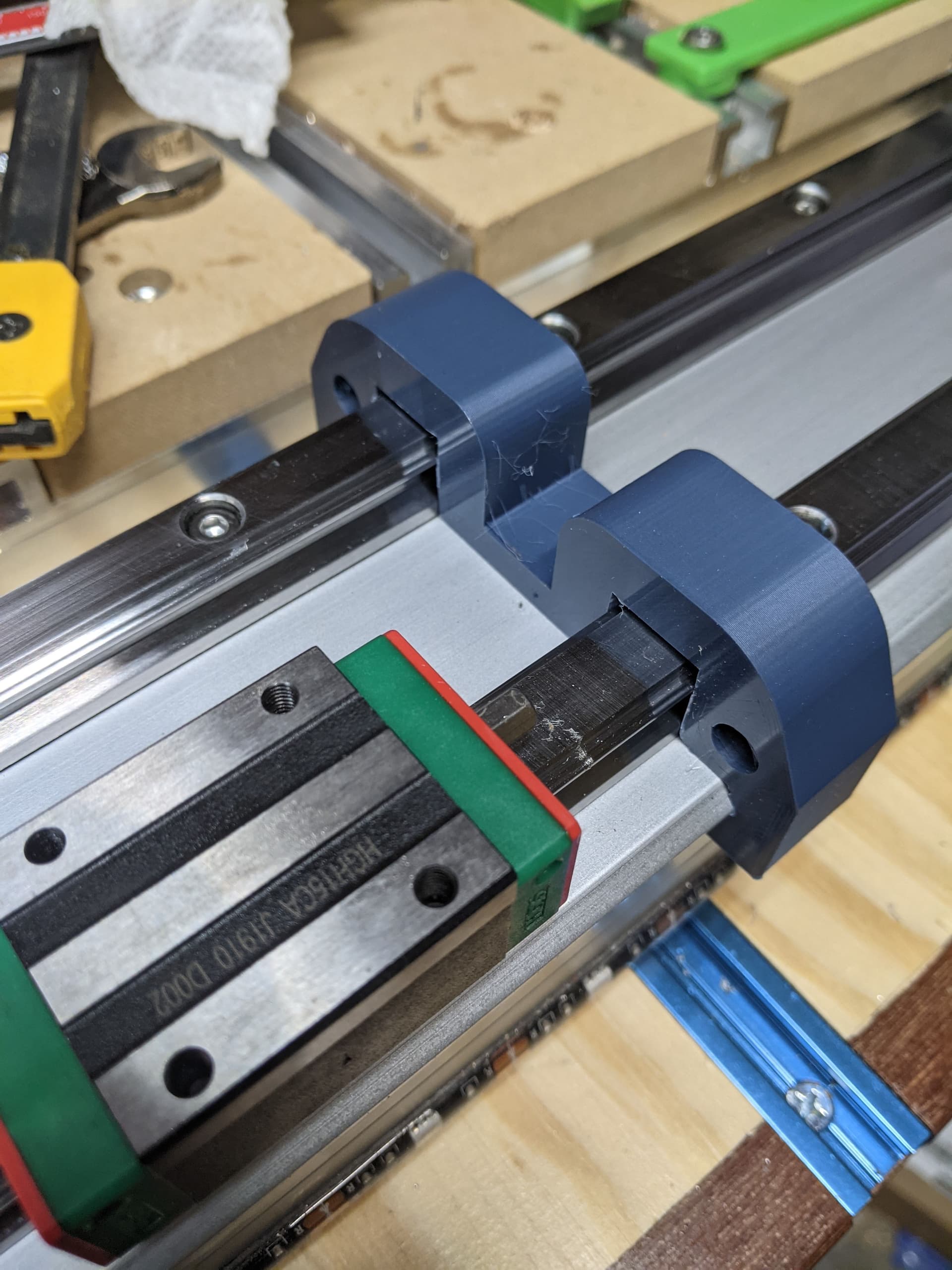
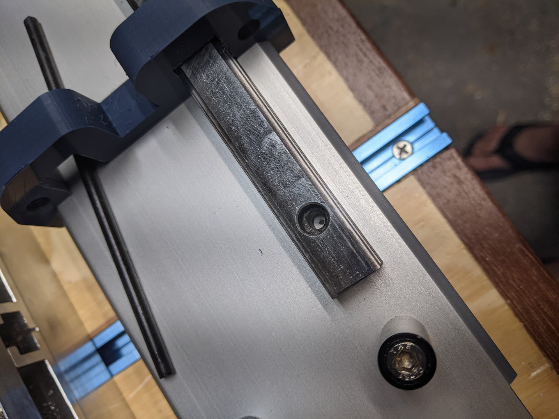
Here you can see how nicely the jigs align the rail:
This is one of the burly ones, it appears that there are gaps around the rails but that is just a shadow. The rails don’t move.
The process of installing the rails is roughly as follows:
-
Clip one rail onto the extrusion and align it horizontally. I spent some time with the dial indicator to get an idea of the variation as well.
-
Move the portable jigs around each hole and use a 4.5mm transfer punch to mark the outer holes for drilling.
-
Remove the rail and carefully drill the two holes. After drilling some not so straight holes I quickly designed a drilling guide and took 30 min to print it. I also tapped the holes.
-
Reinstall the rail and use m4 screws to fasten it, then use the guide jigs to align.
-
Use the transfer punch to mark the rest of the holes, drill them, and tap them. Easy! Actually this is the most tedious and critical part. Here you can see the mark left by the transfer punch in the hole:
-
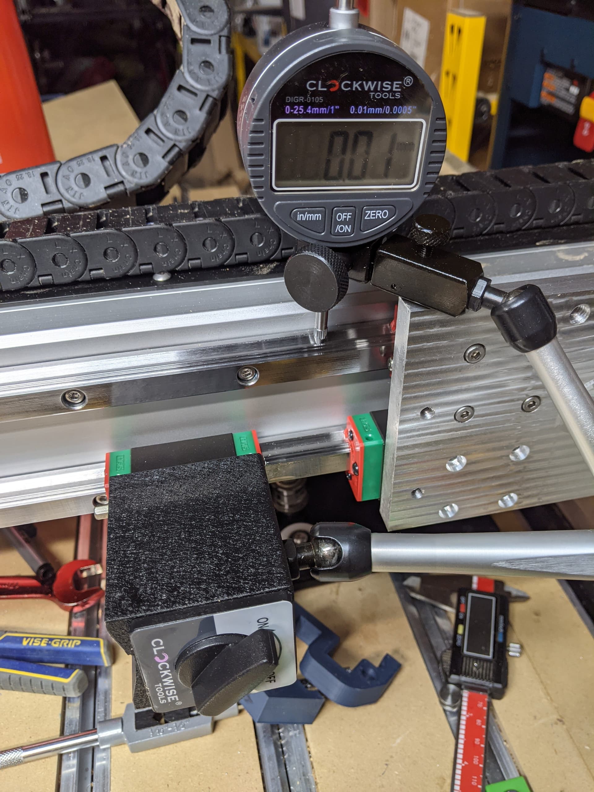
Since 3d printing is perfect I didn’t bother doing any alignment. Just kidding. I put the dial indicator to work and carefully aligned the rail to the top of the extrusion. This is using the assumption that the extrusion is straight to begin with but since the machine ran on it for alignment already I figured that was good enough. Sometimes the jigs were purely magic and zeroed out the rail in the center (it was .35 before dropping them in):
-
Once the top rail was good I used all of the jigs to align the second rail and repeated the process of drilling and tapping. I installed all the m4 screws, with blue loctite as well.
-
Then I spent about an hour using the dial and the jigs aligning the second rail to the first rail. I actually found the jigs were easier to get general alignment than using the dial and messing with each screw with hand pressure. I was pretty surprised just how much accuracy offered. Once I was within 0.02mm across I used a bike torque wrench to tighten them all to 3nm.
-
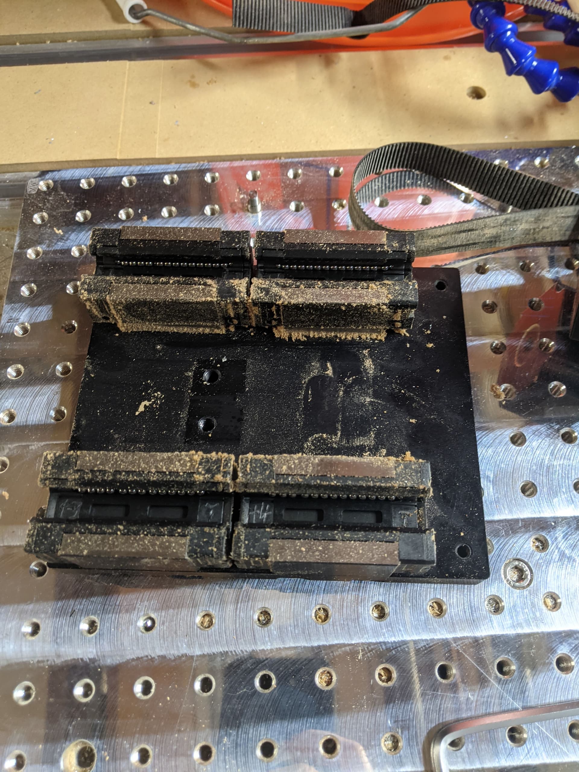
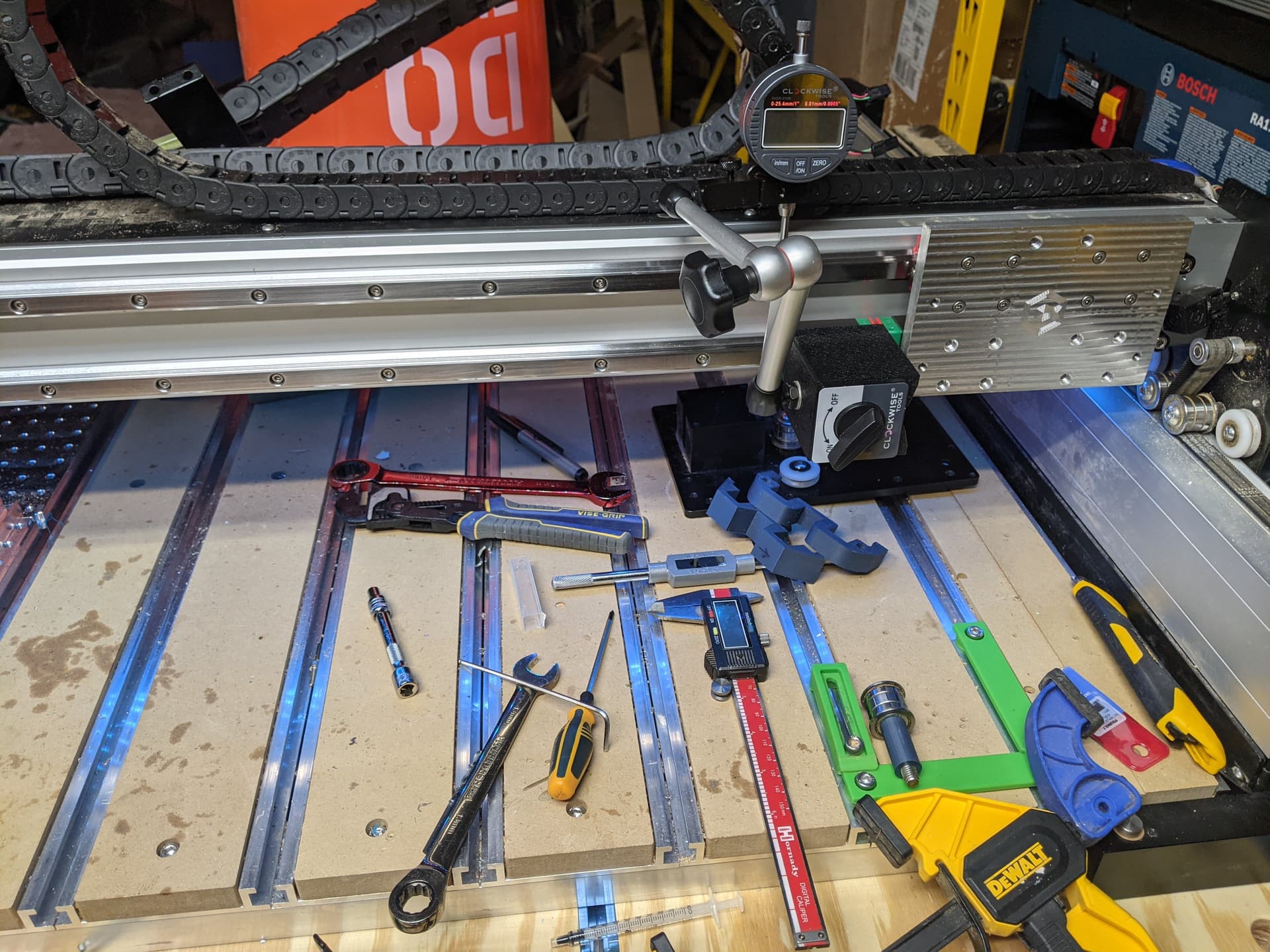
I reinstalled the extrusion on the machine. I actually left the endplates on the machine and just pulled the extrusion originally, this worked out pretty well but I was dreading it at first. Then I installed my plate to test it, pulled one block off and tested the alignment again. They were within .01mm across!

Next steps:
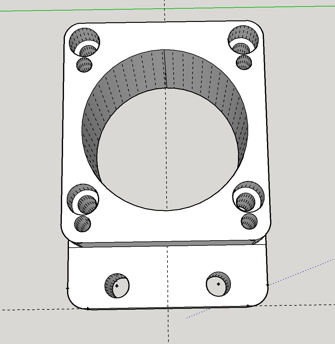
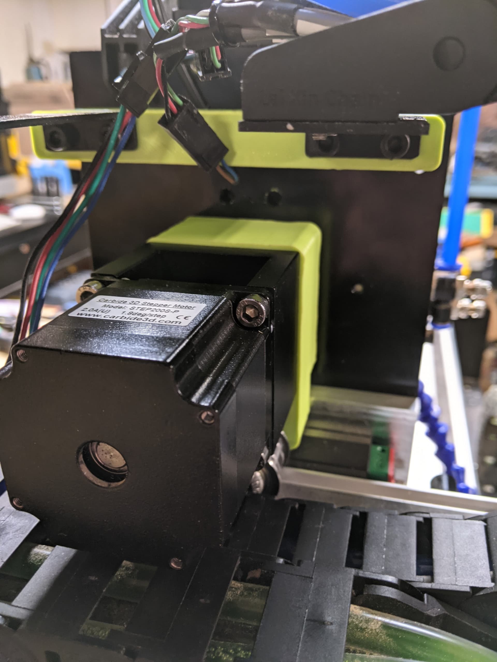
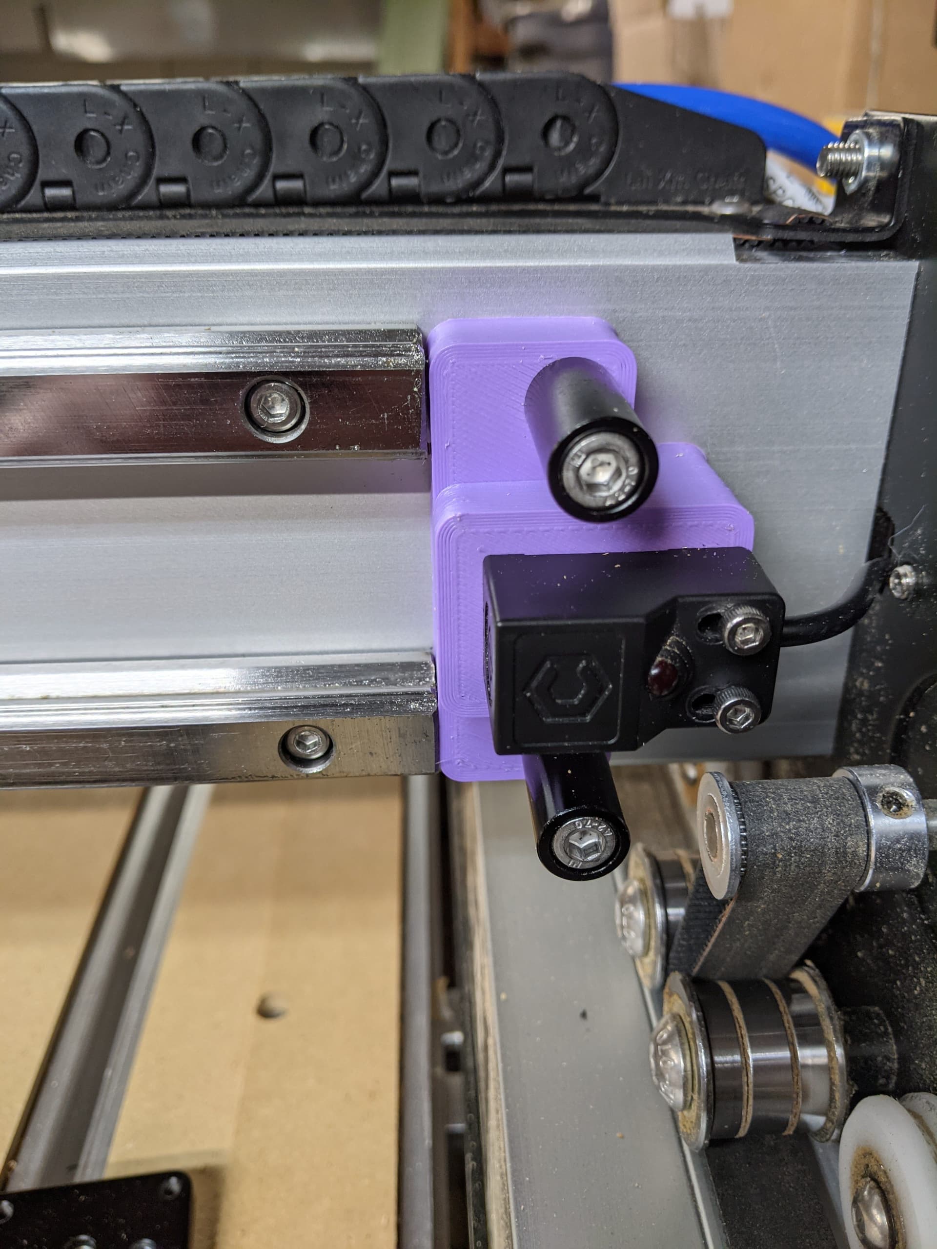
After getting the plate on the machine I discovered that my pulley m8 holes are in the wrong location. I made a bet by using the Pro location and it did not pay off. I’ll design an adapter to 3d print for now until I can mill another plate. I’ve designed some of the adapters for the Z-Plus already, but I need to do some for the drag chain mounts. I’ve also noticed the rail blocks are pretty tight and grindy, so I might remove them to clean them out as suggested by youtube.
Going forward I’ll update the thread with my progress. My plan is to release all of my files for the jigs, the plate, and adapters along with a bill of materials so others can use them. But really, don’t buy a 4 with the intention to do this, just get a Pro  .
.
Those 15mm rails look really good on the 4.

 It’s worth taking a look on fleaBay or similar marketplaces to see what’s going cheep.