I have a shapeoko 4 xxl and I’ve been having some deflection issues resulting in visible chatter. I could see the machine physically chattering as it moved the z axis carriage across the width of the machine. So when it cuts in the x direction it chatters.
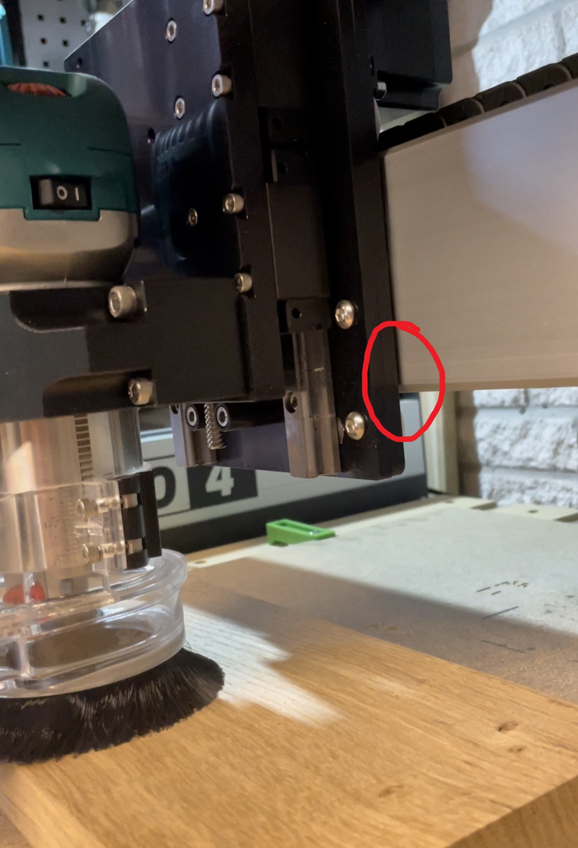
I also noticed when I grab the collet of my spindle and pull on the spindle, the entire z carriage can easily deflect
When I do vcarves and carve text, there is noticeable bit deflection and the carves are coming out sloppy. I’m using a 90 degree Amana v bit at 90ipm 0.2” doc 18k rpm (water cooled spindle). This is what is recommended on the amana tool sheet that came with my bit set. Is this too much?
Belts are nice and tight (but not too tight!)
Vwheels are adjusted to hiw Winston Moy explained in his videos. Everything seems to look good but there is still noticeable deflection. Any advice?
No, it sounds about right, depending on wood hardness. 0.1" would be the comfort zone, you may try that but I suspect the problem will remain.
Can you double-check if all four vwheels of the X/Z carriage are snug against the X rail, and none of them spins freely when you grab the collet and pull on the spindle to the left/right ? Visually inspect if any of those four wheels is damaged (any cracks/flats ?) or worn out ?
The cases I remember where folks reported issues along the X axis turned out to be due to vwheels
If you can grab a video (of the play when pulling on the collet and/or of chattering during X travel) that may give us some additional clues too.
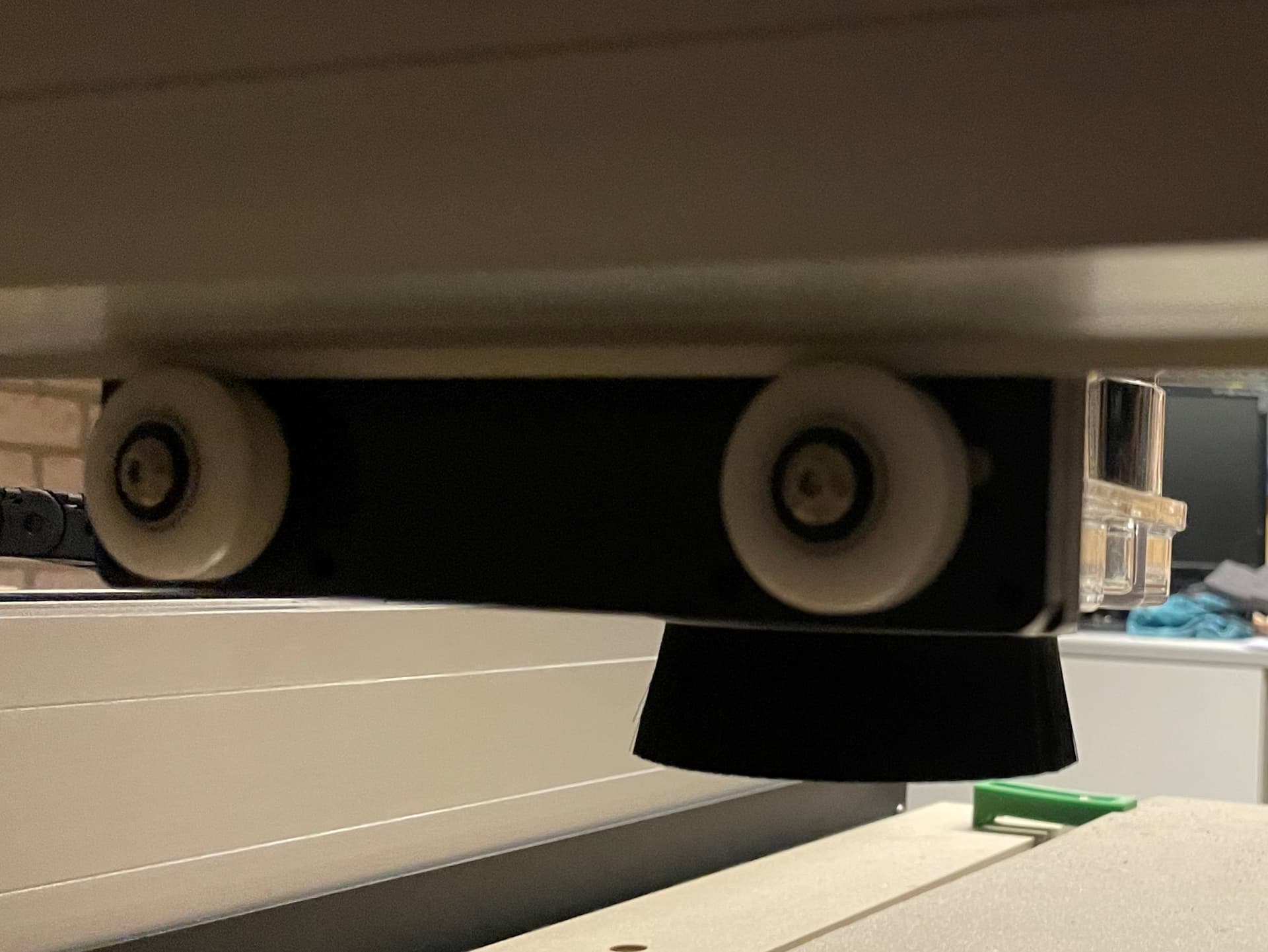
The vwheels are all snug against the rails. There is play from front to back. And a little bit from side to side
The table I have the shapeoko sitting on isn’t perfectly flat but I have supports under the table pushing the 3/4” plywood material up in areas where there was sagging. The entire x rails v wheels are snug on each side. The x-rail seems pretty solid and does not deflect so the deflection seems to be localized in the z axis carriage. I’ll post a video later as I’m at school all day until 9pm! I might be able to run back home and grab a quick video. I’ll try and do a cut to show the chattering. Maybe a slow motion video???
If you continue to have trouble tracking down the offender, I’d suggest, if you have a dial gauge, measure, if not then try finger across the gaps and try to feel where the deflection is happening one motion joint at a time to localise it.
With the machine powered and stationary do your wiggle test and measure / feel between
Spindle and the moving plate of the Z carriage
The moving and fixed plates of the Z carriage
The fixed plate of the Z carriage and the X extrusion rail
The Y plates at the end of the X rail and the Y extrusion rail
The resolution at which a human finger when sitting across a gap can detect movement is surprisingly good…
I later found that the screws holding the v-wheels where loose - they’ve probably been since I assembled the machine - maybe I missed an instruction in the video…
You can’t upload a video directly, do you have a file/video sharing account of some kind ? (Youtube, google drive etc). You could post a link to the file.
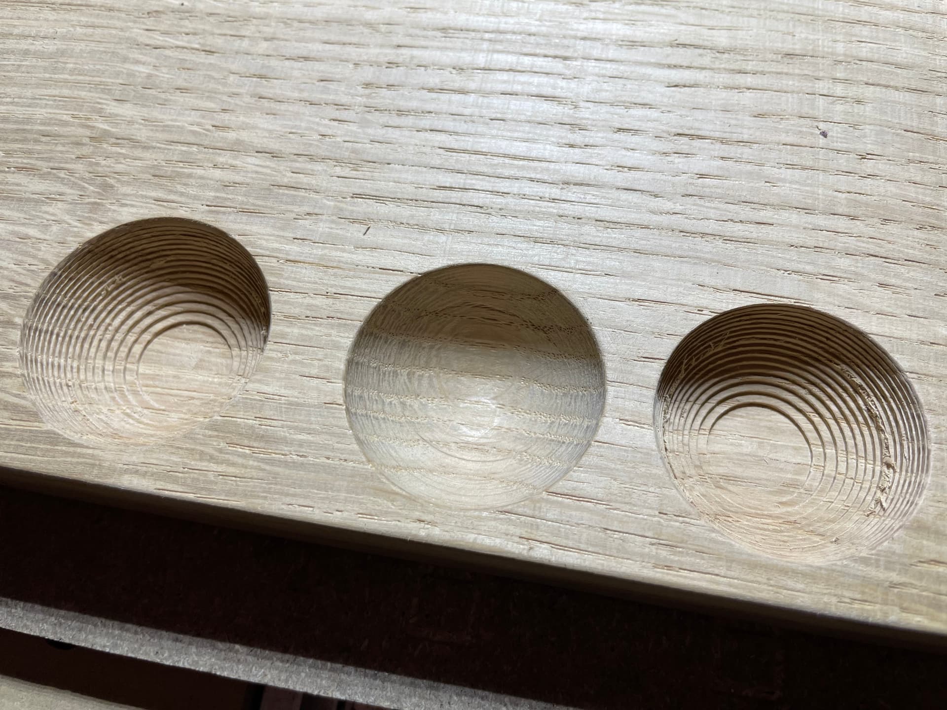
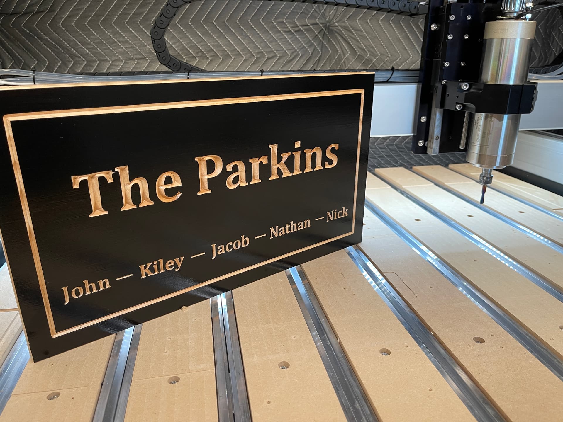
Here are some photos of a sign I made. You can see the “t” in “the” isn’t flat across the top of the letter as the bit has seen to deflected. This is also reflected in the rough cuts on the rest of the letters. The large letters don’t look as precise as they could be.
I checked the z axis gantry. The plate moves farther and closer to the gantry as I apply some force on the collet. It seems the vwheels are deflecting somehow?
Yes, I can now see the video and confirm this is not right, way too much play.
does any of the four vwheels spin freely ? You said they are “tightly bolted in” but I’m not sure if you meant that you checked they are all against the rail, just enough that when running your finger over any or them with the power off, the gantry moves
inspect them really closely: could one of them be split in the middle? sometimes it is hard to see until you look really closely, because the two halves are still held in place by the screw.
are you sure the deflection happens at the vwheels, not anywhere else in the X/Z plates assembly ?
Please systematically remove items from consideration — I like to work from large–small:
are the endplates level and parallel to each other? All fasteners secure?
are the Y-axis rails level and parallel and at right angles to the endplates? Fasteners secure?
Is the X-axis gantry level and plumb and at right angles to the Y-axis rails? Fasteners secure on it? Is it guided by the V wheels so that it can only move backwards–forwards and can’t shift up/down?
is the carriage level and plumb? Is it also held along the gantry by the V wheels so that it can only move side–side and can’t shift vertically?
is the Z-axis carriage spindle plate well connected to the linear rail blocks of the Z-Plus so that it only moves up/down guided by the rails when the lead screw is turned by the motor?
is the router mount secure? Level and square to the carriage?
is the router secure in the router mount? Is it held plumb in the mount?
is the endmill well secured by the collet? Does the collet fit the shaft of the router securely? Does it turn true when turned?
Basically check everything per:
Let us know what you find out at support@carbide3d.com if there is anything which cannot obviously be addressed by adjustment and we will do our best to assist.
I just did some squaring and loosened the y rail carrier plates and frame screws. I checked all vwheels on both sides of the y axis and they seems to have a consistent smooth roll whether the gantry is at one side, the other, or anywhere in between. After doing this the issue still exists but it doesn’t seem as bad as it was. I would say the issue is 20% gone. Tomorrow I’m going to take apart the z axis assembly and see if I can fine tune the vwheels and double check EVERYTHING. I will have more to report on tomorrow.
Ok so I took the z axis gantry off and took off the vwheels and inspected them. They look perfect. I have almost zero play on the x/z overhead carriage as it moves back to front. From side to side however, the z axis seems to have a lot of play. I’m trying to tension the belts a little more on the x axis but it’s very difficult as the belt keeps slipping in the bracket when you go to tighten it down. The belt is decently tight right now and shouldn’t be a problem.
When I first put it on when I got the machine, the vwheels got gouged by the corners. I had to rotate the eccentric bits to bring them out a bit. Not sure if this would contribute to the problem.
It could be, if this resulted in one (or both?) of the vwheels spinning freely when you run your finger over them (as Will noted they should all contact the rail, for proper operation of the machine). If you lift the while X/Z gantry vertically, can you see the top vwheels lifting slightly from the rail ?
Regarding the clearance between the vwheels and the belt clips, you should be able to angle the anchor slightly to the side while tightening, to clear the wheel. Make sure to push downwards with your thumb onto the clip and belt as you tighten, to avoid the slippage. Depending on tolerances this may or may not be enough. I had a similar issue at some point and decided to Dremel a mm off the side of the belt clip (but that’s just me, support would likely not recommend that )