I am hoping they get me tracking info soon. He said he would get it expedited, but no word back yet ![]()
Just to clarify, are you saying the spindle goes to 24k RPM as soon as you turn on the SO5 and before you connect it to carbide motion?
If this issue happens only when you connect to carbide motion, then I recommend you try using a different g-code sender and see if the problem still exists.
Do you have a multi meter to do some troubleshooting with? You can check to see if you get 5V from the pig tale between the white and black wire when the SO5 is turned on but not connected to CM. If you are getting a sustained 5V from the SO5 upon turning it on, then you most likely have a bad SO5 controller.
You can also check if there is a grounding issue on the VFD box by using a multi meter in resistance mode with everything turned off. You would place one probe on the black wire going into the VFD box and the other probe on the metal housing of the VFD box. You should read close to 0 Ohms.
If you spindle is ramping up to 24K RPM as soon as you power on the SO5 controller then it seems to me you have two possibilities.
- SO5 controller is bad and is sending a constant 5V signal to the VFD box.
- Grounding between the SO5 and VFD box has a potential difference of greater than 5V. (Very unlikely)
This is exactly what happens. Support decided a new VFD is what is needed. I am still waiting to know if they shipped it out yet or not.
I really think you should check to see if you are getting a constant 5V between the black and white wire going from the SO5 controller to the VFD box. If you are, then a new VFD box is not going to fix the issue.
1 Like
Thanks, I will see if I can get a hold of a multi meter.
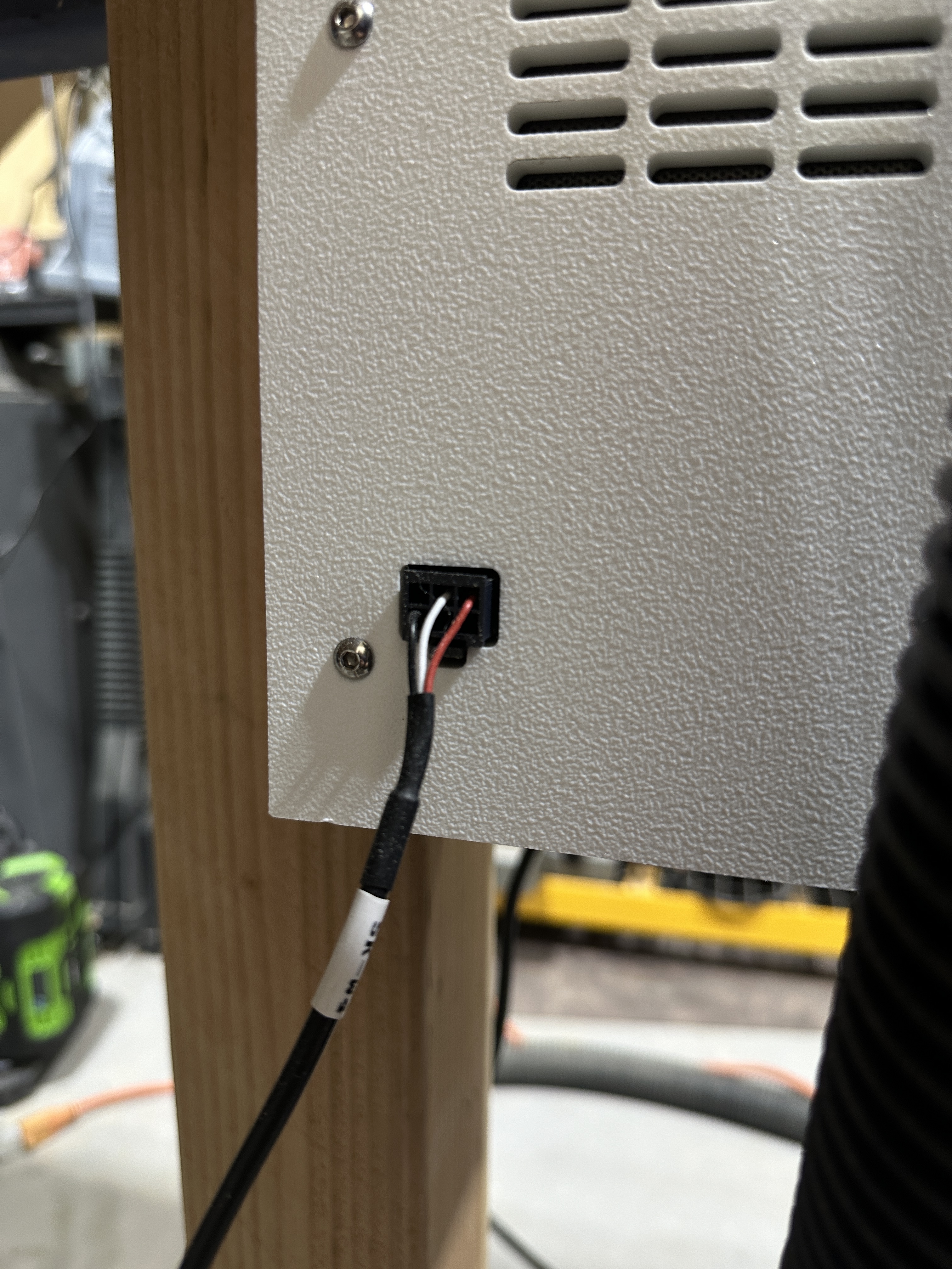
I found one. You are talking these wires right?
I have never done this before, any tips for how I test that?
Yes, If you unplug it from the box you can probe the white and black wire. Black is ground, white is PWM signal, red is +24V.
Set the meter to DC mode when probing.
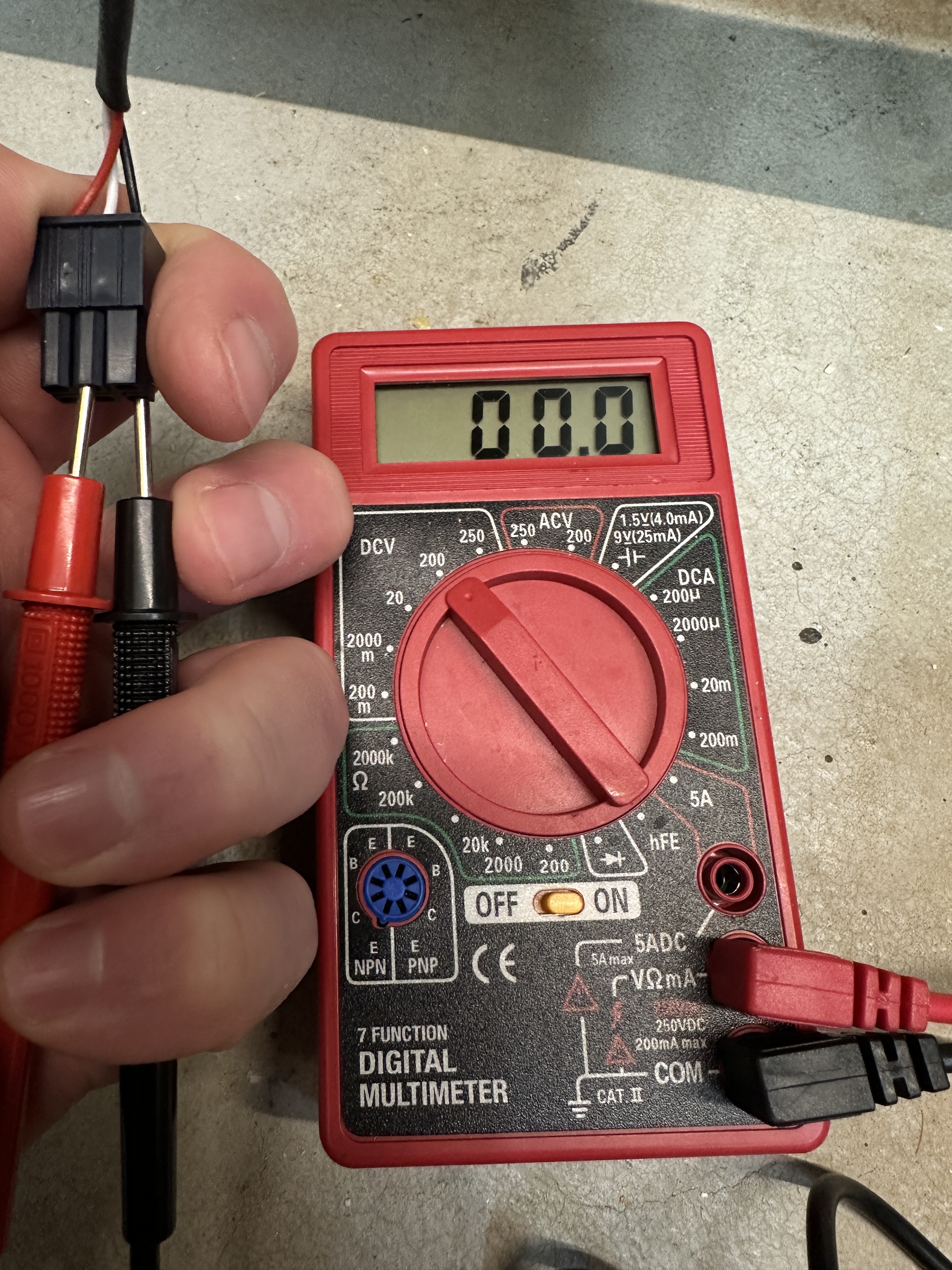
So with the SO5 controller turned on but not connected to carbide motion you should get 0V when probing between white and black. You should also get +24V when probing between black and red.
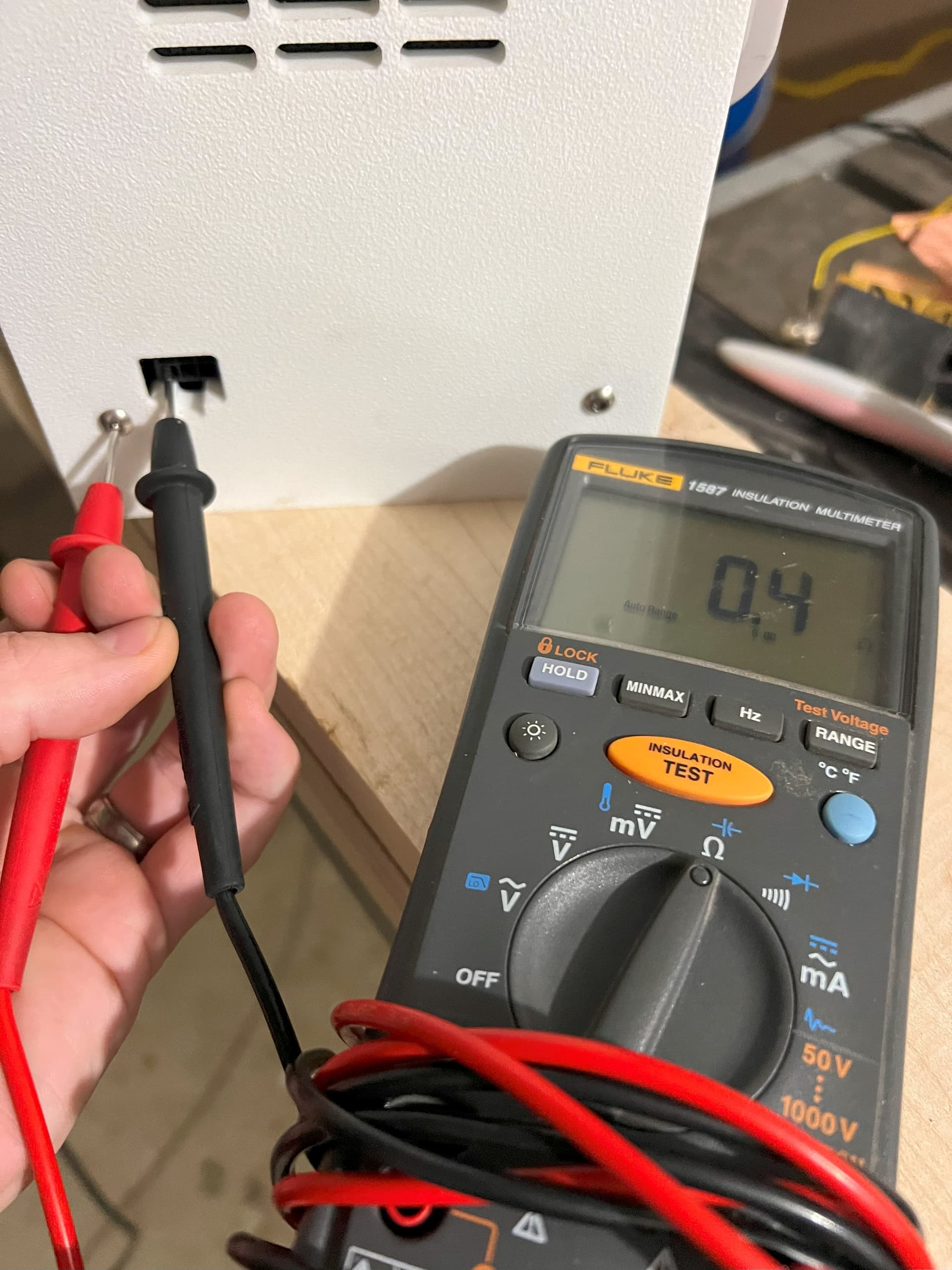
For resistance checks the machine must be turned off to avoid damaging your multimeter. You can put one probe on where the black wire would go into the VFD box and the other probe on the metal housing. You should read less than 1 Ohm and not OL(open lead).
2 Likes
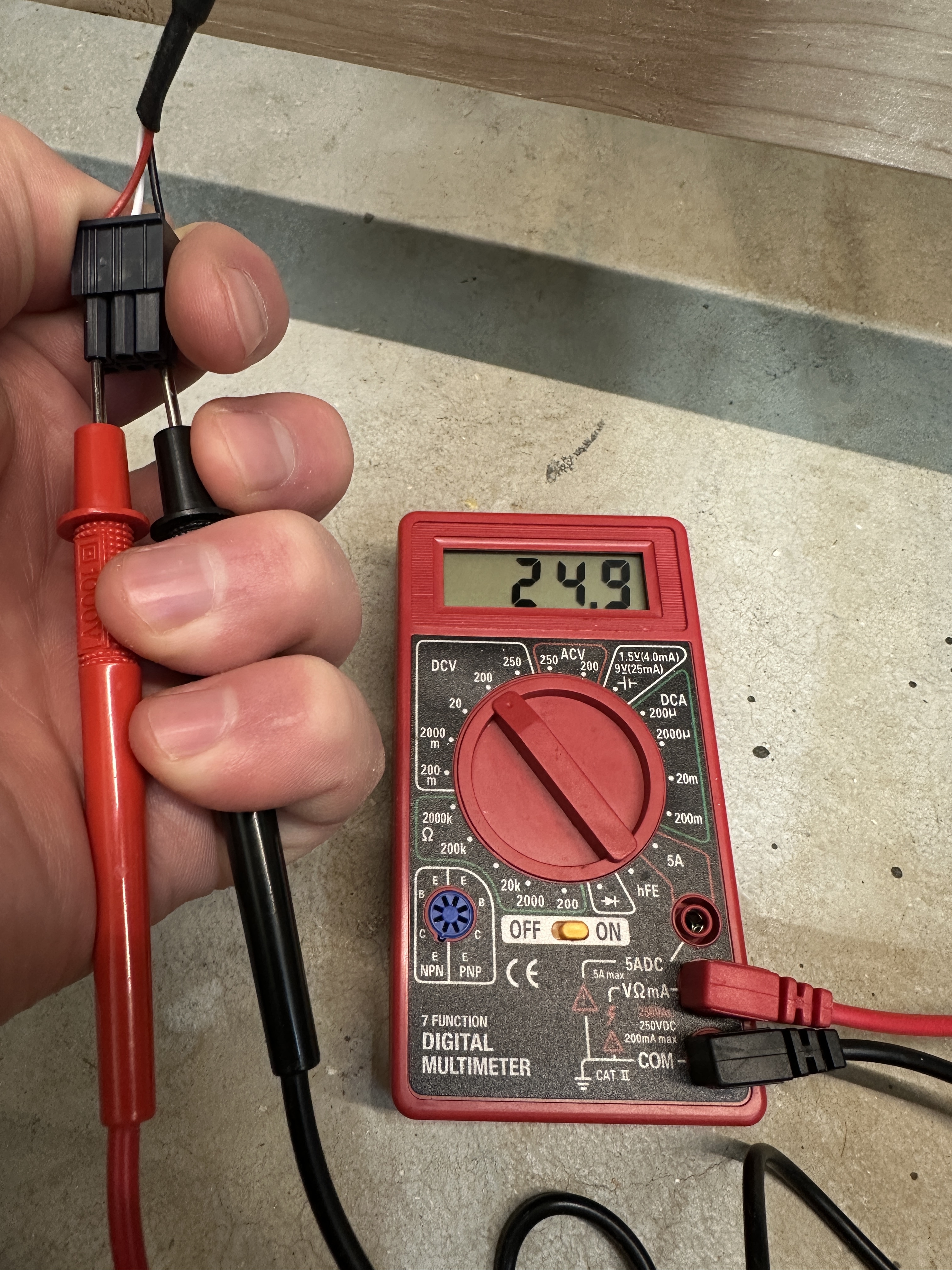
Yes that looks normal. You could try setting the meter range to 20 instead of 200 when testing white to black however to make sure you are getting the best reading. What do you get when you probe on the VFD box where the black wire would go and then the other probe touching any of the metal housing?
For the resistance check remember to have the machine powered off and it would be best to set the meter to the 0-200Ohm range as that is the lowest it looks like your meter goes.
1 Like
It doesn’t get any sort of reading. I tried moving it to all the different settings on the multimeter Ohm settings.
Does your DMM display OL when the probes are not connected to anything or 0?
Example: Probes touching each other reads 0. Probes not touching anything reads OL or anything other than 0?
1 Like
Are you saying connect all the wires back up and check? I left the cable unplugged from the SO5 controller to the VFD. I stuck the probe into where the black wire would go in and the other end to any part of the metal housing. It didn’t get a reading. It just shows a 1 on this multimeter.
The VFD light is also not on at this point. I made sure to have that powered off, but plugged in.
No need to hook any of the wires up or power anything on. I am just trying to understand what your multimeter reads for resistance when its open vs short. Here is a example picture.
when you connect your two probes together do you get a reading of 1? It might just be the lowest your DMM goes.
2 Likes
I just realized I was testing the wrong point on the vfd. This is what I see when I put my multimeter in the way you are showing :

Yeah looks like you have a bad ground inside the VFD. So replacement should fix.
I super appreciate you taking the time to teach me a little about how to test for these things so I can have more data when I reach out to support if I should need to in the future.
@WillAdams any chance you can DM me the status of my vfd replacement?
Apparently, now I got a call, and they aren’t sending a new VFD. They are sending me the internal controller if I feel I can do the repair myself. ![]() . I wish I had known this Monday and now it is Wednesday. I was expecting the new VFD to show up any time now.
. I wish I had known this Monday and now it is Wednesday. I was expecting the new VFD to show up any time now.
Glad they finally wised up and are sending out new spindlerella PCB boards instead of swapping the whole VFD kit. It will probably save them lots of money in shipping alone in the long run.
It is 3 connectors and some screws holding it in. Shouldn’t take the average person very long to replace. Main thing to remember is that you will want to leave the VFD unplugged for 15 minutes before opening it as there are some large capacitors in play here. Best method would be to check for voltage between load and neutral with a multimeter before opening.
4 Likes
Thanks to both of you. It sounds like I received my Shapeoko about the same time you did, with the same problem. I just checked mine with the multimeter and got the same results. Now, if carbide support will email/ call back.
I am sorry to hear you are having the same issue. Make sure to get pictures and send it to support. I know Will keeps a pretty close eye on things and he might be able to see where your ticket stands.
I just got my shapeoko on Sept. 8th.