That’s not my intention. I was hoping that it would help people (including me) better understand what I consider to be the basics. Maybe this will help with that.
Since you’re a retired woodworker, I imagine that you have experience using routers. With router bits less than 1” diameter, you probably use the maximum speed supported by your router (22,000 – 30,000 RPM) because you can advance (“feed”) the router or workpiece faster without pushing harder (increasing the “feed” force). My default router table “feed rate” seems to be around 100 inches per minute (IPM) and my router’s maximum speed is 25,000 revolutions per minute (RPM). So, the workpiece advances 100/25,000 = 0.004 inches per revolution. So, with a two-flute router bit (or endmill), the workpiece advances 0.002 inches per flute/tooth (IPT) - that’s the “chipload”. If the workpiece shows signs of burning, I decrease the depth and/or width of cut to safely enable a feed rate increase. A typical 10-inch combination blade for a table or miter saw has 40 teeth and spins at 3450 RPM. A 100 IPM feed rate produces a 100/3450/40 = 0.0007 IPT chipload. Recent experience suggests that chiploads of about 0.001 IPT are acceptable for almost everything that folks use Shapeokos (and Nomads?) for (so enter 0.001 in cell D10 of the workbook’s “Working Spreadsheet”).
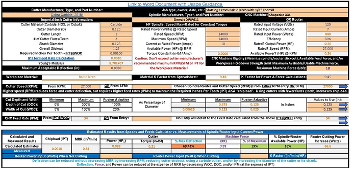
Properly operated power tools do all the cutting work, the operator (or CNC machine) just positions them. Positioning them properly requires that the operator or CNC machine counteract the cutting/milling forces generated by the tool. (Most of the force produced by routers is perpendicular to the feed direction - i.e. toward the fence on a router table.) The amount of force produced by the tool can be calculated from the magnitude of power it uses when cutting/milling. The magnitude of that power can be calculated from the material removal rate (MMR) if the material’s K-factor (cubic inches per minute of material removal per horsepower (HP)) is known (and entered in cell J15). It can also be approximated from the measurement/entry of the tool’s input power when not cutting/milling (cell D32 of the workbook’s “Working Spreadsheet”) and when cutting/milling (cell H32). Note that other sheets in the workbook show known(?) K-factors and your Janka hardness values – thank you for that!
The maximum amount of allowable machine force used for the calculation of the cutting/milling parameters can be entered into cell J13 of the “Working Spreadsheet”. The default value of 18 lbf is reportedly what the standard X-axis stepper motor can provide. The usable value will be far less than that due to the lack of machine rigidity. That lack of rigidity causes the cutter to be deflected from the intended position due to force exerted by the cutter. Deflection vs force is easy to quantify with a luggage weight scale and a ruler or calipers when the machine is on with a stationary unpowered router. I’d be reluctant to enter more than 3 lbf for starters in cell J13.
The cutting force on the endmill will also cause deflection/bending. The amount of allowable deflection (at the end of the endmill) is entered into cell D13. Too much deflection will break the endmill, but 0.003 inches is likely plenty safe, at least for 1/8” endmills and larger. (That’s probably more that an order of magnitude less than machine flexure induced deflection.) Other required information about the endmill is entered into cells D4 – D9.
Entries in rows 1 - 3 of the “Working Spreadsheet” aren’t necessary but may prove useful for documentation and sharing purposes. (I hope you do both.)
If you use a HF Spindle, leave/make cell J4 blank and enter the spindle’s info into cells G5 – G8. If you use a router, leave/make cell G5 blank and enter its voltage and current ratings into cells J4 and J5 respectively. They’re more indicative of actual router output power than the advertised router power. Leave J7 at 50% unless you know otherwise. Enter your router’s maximum speed into J10.
Some manufacturers specify endmill maximum operating speeds as the tangential speed of the cutting edge expressed in Surface Feet per Minute (SFM) rather than RPM. If SFM is entered into cell E17 when cell C17 is empty/blank, the resultant spindle/router speed will appear in cell J17. Recent experience suggests that maximized cutter or spindle/router speeds are best for virtually everything that folks use Shapeokos (and Nomads?) for. I usually don’t use endmills from manufacturers that don’t provide speeds and feeds information, they may not be safe.
The desired depth and width of cut (DOC and WOC) are entered into cells J21 and J22 respectively. IMO, a good/safe starting value for DOC when cutting slots (i.e. DOC = WOC) is the endmill diameter for all but the hardest of woods. Since MRR (and force) decreases proportionately with width of cut, DOC can be increased accordingly as the WOC decreases. I.E. a DOC of twice the endmill diameter with a 50% endmill diameter WOC seems appropriate.
The entered WOC, endmill diameter, and required chipload are used determine an IPT (cell D11) for the feed rate calculation that compensates for the “chip thinning” when the WOC is less than 1/2 the endmill diameter. That feed rate, shown in cell C24, can be over-ridden by an entry in cell E24.
I hope this helps. Try it, you might like it! Help me improve and/or explain it? Feedback from anyone of any type is welcome and encouraged.![]()
2019-08-04 Speeds and Feeds Workbook.zip (168.3 KB)
