I’m new to the Shapeoko and would like to know if what I’m seeing is normal or if there is an issue on my machine. It seems like the machine is stiffer when force is applied to the endmill in the X direction than in the Y direction.
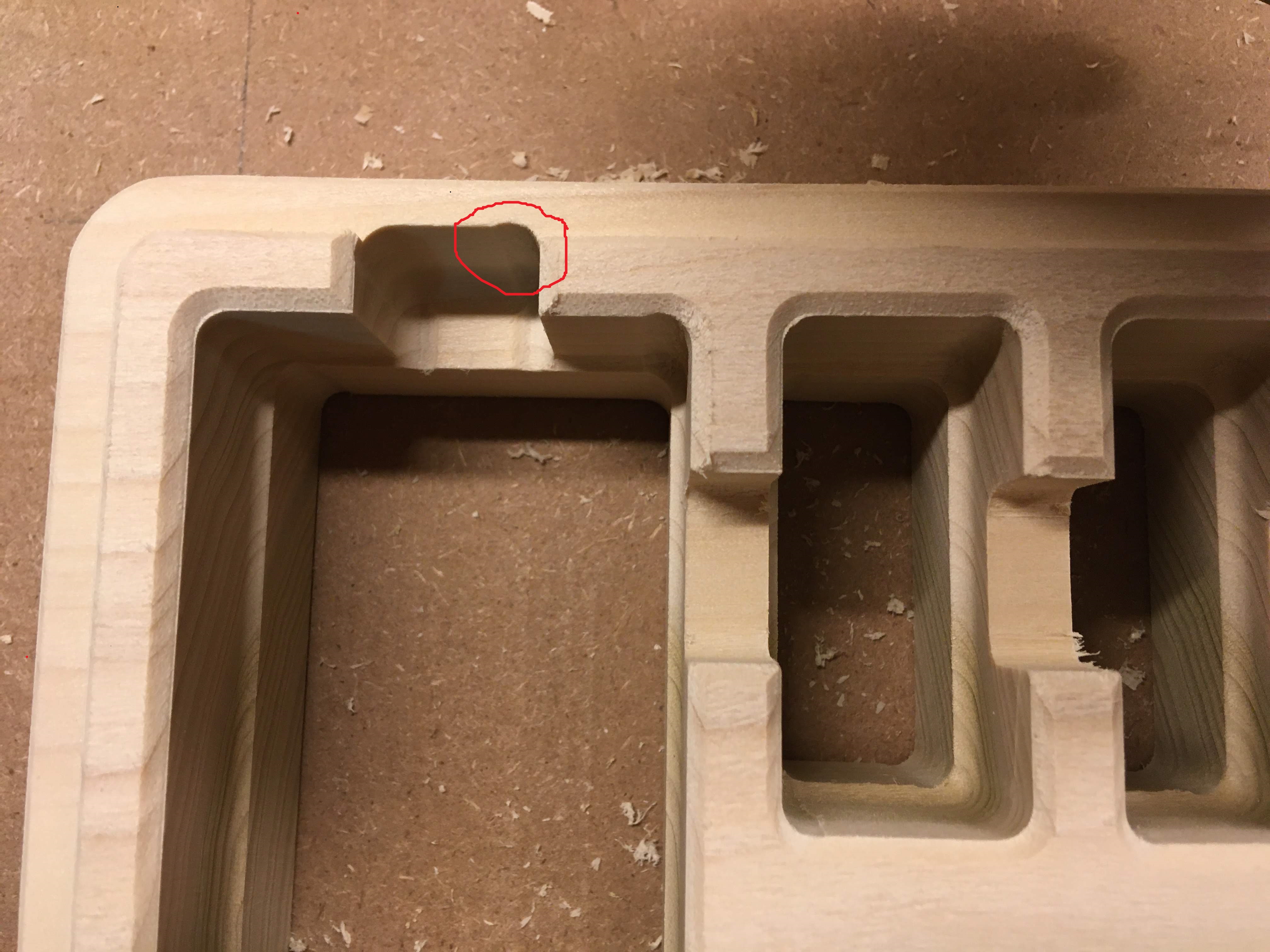
In my current project, I’m clearing out deep pockets with climb cut wide-shallow cuts, then finishing the pockets with conventional cut deep-narrow cuts. I’m trying to follow the outstanding A to Z guide that @Julian put together (Seriously, bravo; Its a work of art!) for the feeds and speeds on those tool paths. Note in the attached pictures that the endmill was pulled into the workpiece in the upper right and lower left corners of each pocket and only in the Y direction as evident by the gouges left behind.
Since the pocket radius is exactly half of the endmill diameter, the cutting forces spike momentarily when the endmill enters the corner. I wouldv’e thought that the Shapeoko was stiff enough for this. Designing around that constraint with a bigger radius is fine but if it is an issue with something on my machine, I would like to find that and fix it. All of my V-wheels seem tightened down sufficiently. Anyone else experience this?
did you see if the overcut (circled in red) happens during the shallow pocketing passes, or just when you run the (full depth?) finishing pass on the walls ? where in the pocket are you plunging ?
can you provide your feeds and speeds (and ideally the design file for a quick look)? What wood is this ? (reminds my of beech, which is HARD)
what endmill are you using and how much does it stick out of the collet during the pass where this happens?
Generally, you should be able to do corners of the same radius as the endmill (though it’s usually recommended to pick a slighty larger radius than exactly the endmill’s), so let’s see if it’s something mechanical in the machine (but the rest of the cut looks nice), something in the F&S, and something specific to your usecase here (deep pockets)
My suggestion for avoiding this sort of thing is to leave a roughing clearance greater than the error and then take a finishing pass — some CAM tools do this automatically, but how to do it in Carbide Create can be intuited from the Toolpaths in:
The overcut happens only during the full depth finishing pass. Im doing a 4" ramp plunge along the wall on the full depth finishing pass.
I’ll attach my vectric design file. In these pockets, I’m running my 2 flute 1/4" ball end mill at 23000rpm and 90ipm (though I did turn the feedrade down mid cut to try to remedy the problem to no avail). The full depth finishing toolpath is actually 3 cuts: first and second to a total depth of .9" (.45" DOC, .035" WOC), and the last is a full depth cut with .015" WOC. The wood is nice soft 8/4 poplar.
My endmill is rather long 3" overall and sticking out of the collet by about 1.75". I’m cutting the part as a 2-sided operation. Is that asking too much of the stock Z assemlby?
Also, I would be remiss if I didnt take the opportunity to say: I had a MPCNC with ESTLcam before this current rig and only ever made fine sawdust while cutting. After reading through your A to Z guide, and running this machine, the chips coming off my wood are just perfect. So much good info in there! Thanks for putting that together for us noobs.
I took a long hard look at your file and honestly couldn’t find anything suspicious in the design
feeds and speeds seem correct to me
even though 0.9" is deep, shaving 0.015" off the walls at that depth for that finishing pass shouldn’t put much load on the machine.
the plunge entry and exit points are not where the problem happens, and the ramp would have mitigated that anyway, so no problem there.
I assume your endmill has a cutting length greater than 0.9"?
This project is definitely doable with the stock Z.
Re-reading your previous answer, can you confirm whether you meant that this problem occurs during all 3 passes of the “main tile finish” toolpath, or only during the last pass that removes the remaining 0.015" ?
A few tests you could do to investigate:
double-check if you feel any slop when shaking the Z-axis plate/router front to back ?
run a test cut keeping only the top half of that main pocket (leftmost on the pic) and see if you can replicate the effect?
if so, rotate the design by 90deg and do a test cut, to confirm whether the defect follows the Y axis ?
reduce your X/Y accels ($120/$121) by 50%, see if it changes anything ?
I had the same issue … it was attributed to a v-wheel tighter than the others.
I only discovered the cure when I placed a straight edge and jogged the Y axsis from back to front. That’s when I found that the Y was not tracking straight due to a tight v-wheel.
When I check my v-wheel for proper adjustments I hold the assembly and with my thumb and index fingers I rotate the v-wheel and feel for a slippage/ friction.
This feeling is compared to all the other v-wheel for same feel.
So I went through a lot of the troubleshooting methods you guys mentioned. I also took the z axis apart and tightened/ locktite every screw I could. I think what I’m narrowing this issue down to is my double sided woodworking tape. Since most of the parts I do are longer in X than Y, there’s more resistance to moving the part in the X than the Y direction. My tape is a bit thick so perhaps I need to try the painters tape method that most people here support for more rigidity.
Good to know, thanks for the feedback. It does look a bit thick and prone to lateral play on tall pieces.
As you said, give the tape & glue method a try, I bet you will like it!
Painter’s tape (blue or green) will add about 0.010 to 0.013" under your part. I’ve never seen any movement on my parts.
The seller at your Amazon link states, “The XFasten Double Sided Woodworking Turner and Wood Template Tape is paper-thin, at 0.25mm thick for the actual double-sided tape itself, and 0.08mm thickness for the paper liner”. This double-sided tape is slightly less than 0.010" thick.
The thickness isn’t the problem, but the adhesion may perhaps be.
Good point. It is some soft, gummy tape though and does give me discernible flex when I stick two pieces of wood together and apply a shear force. More than I would think painters tape would move. I’m feeling tempted to order some painters tape and test side by side at some point.
Seems like I’m just approaching the limit on this piece where tape just isn’t a good hold down method for its height and lack of surface area.