Shapeoko on the Rails!

Thanks @WillAdams for unlocking the thread, I just didn’t quite beat the time limit :laughing:

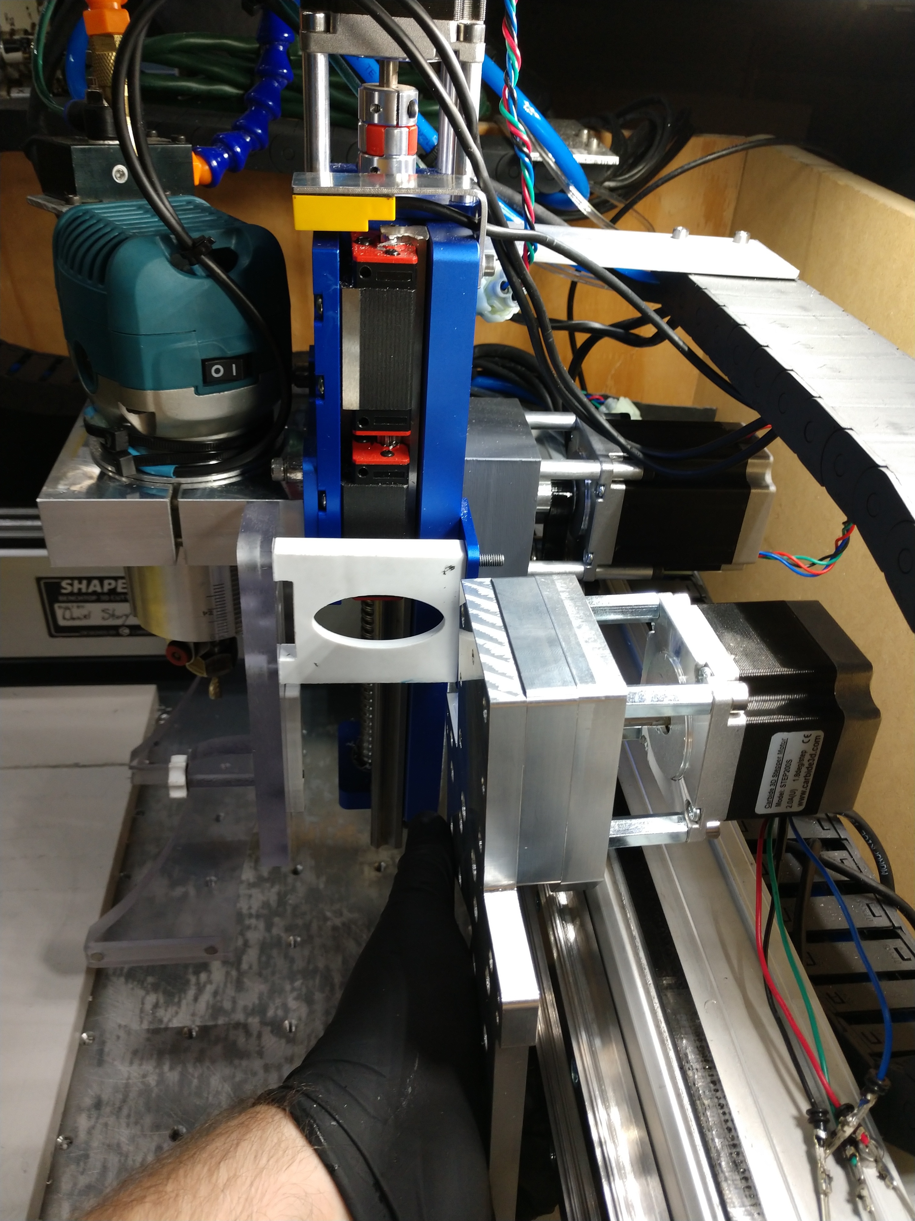
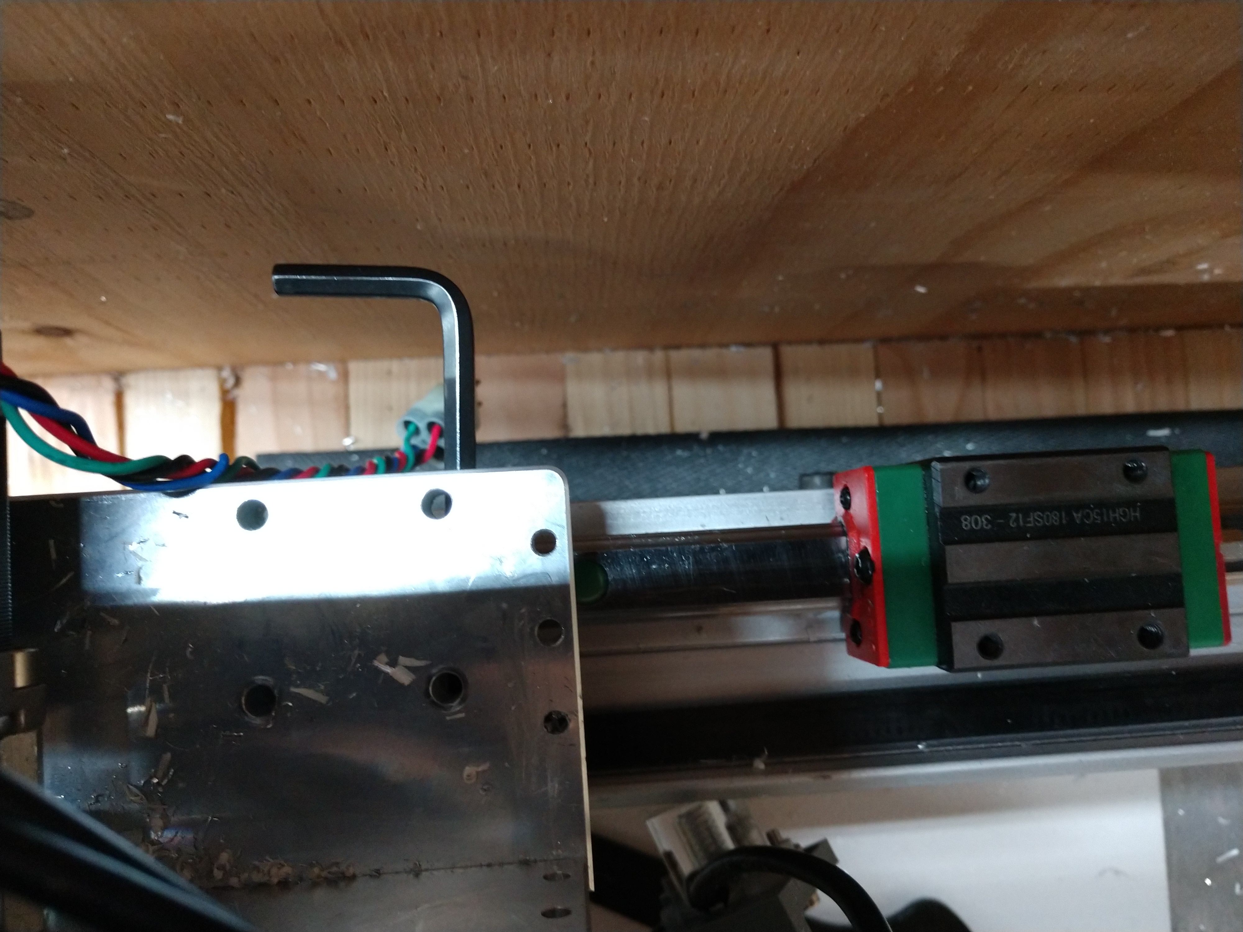
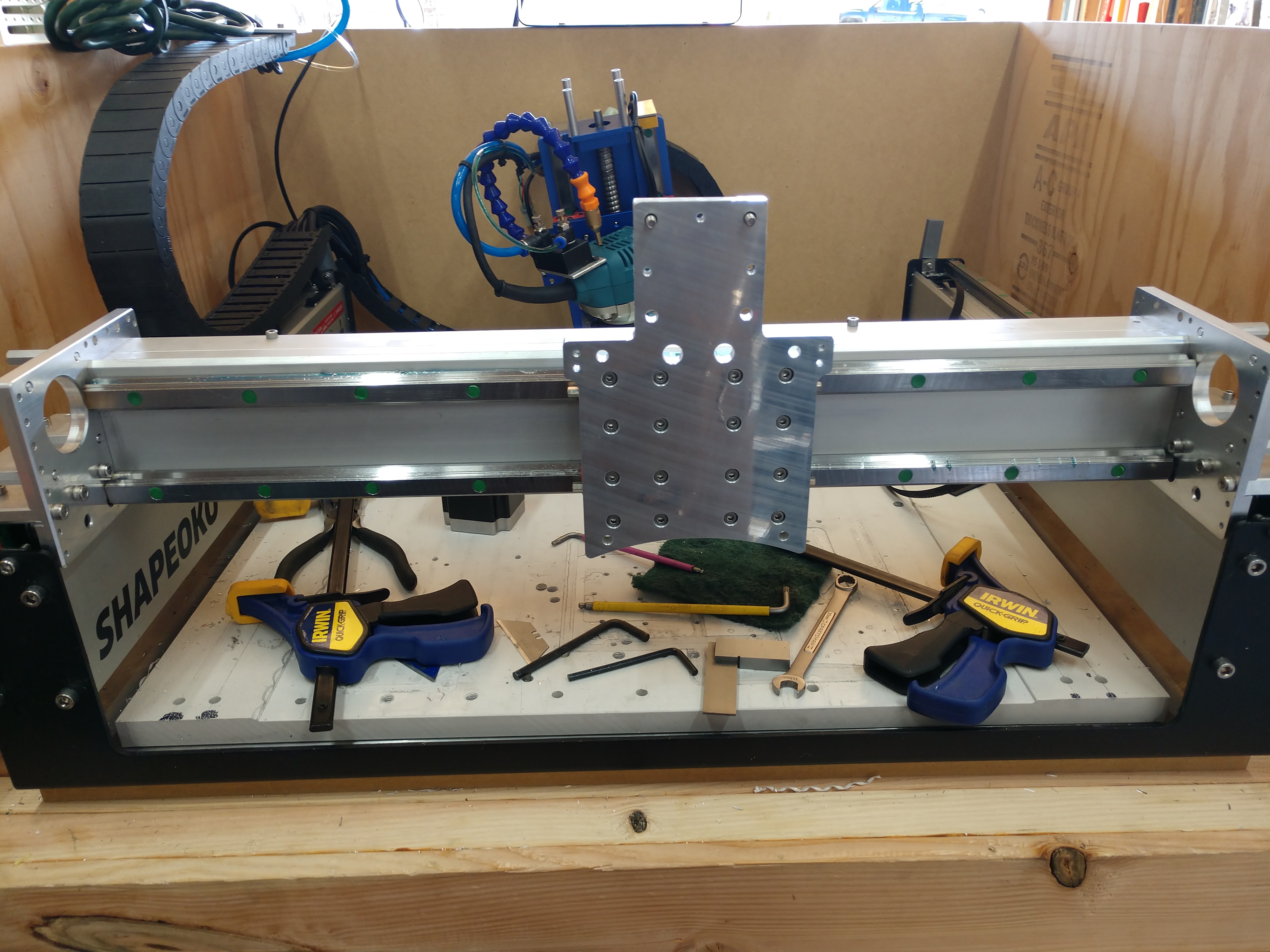
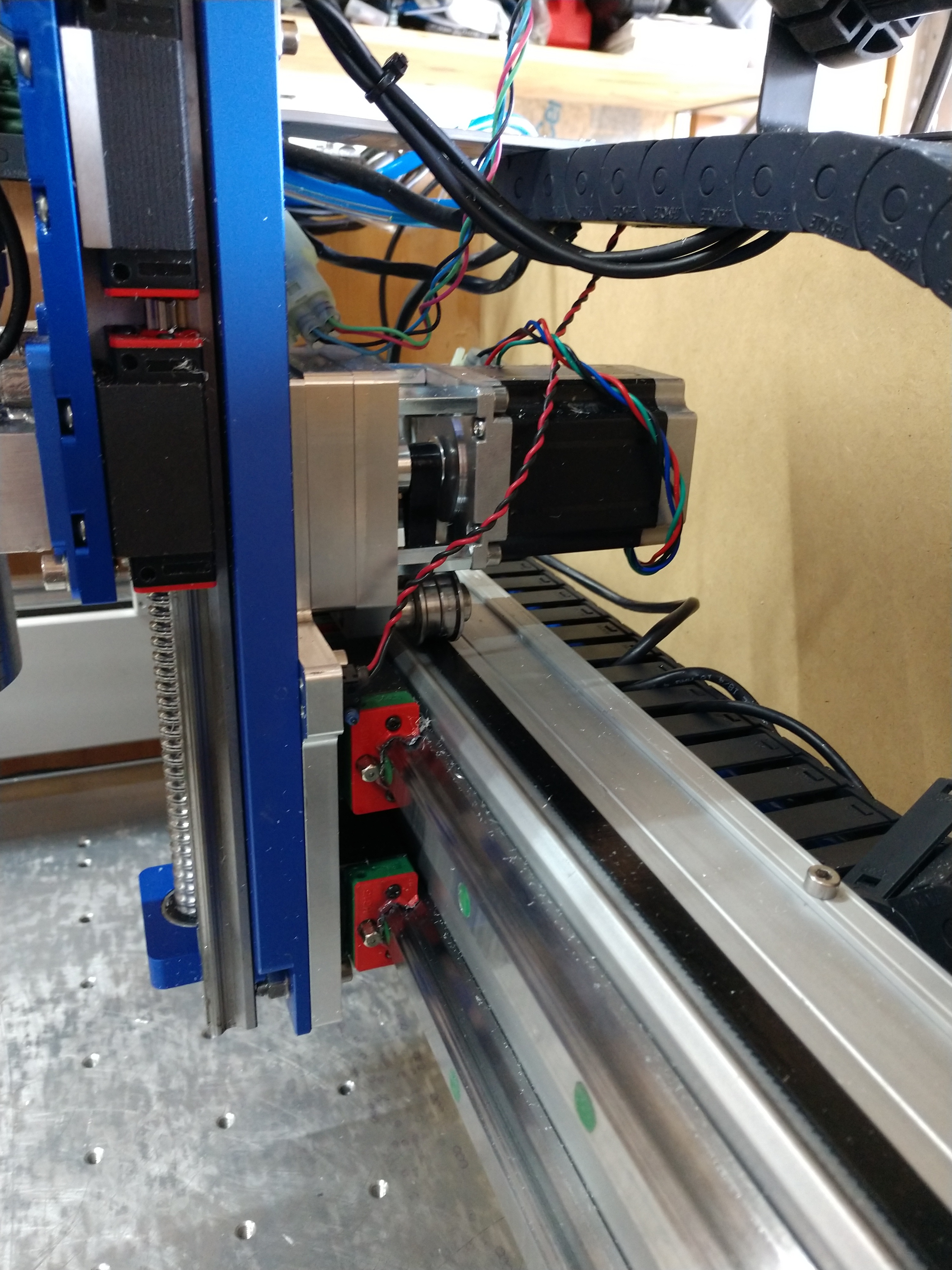
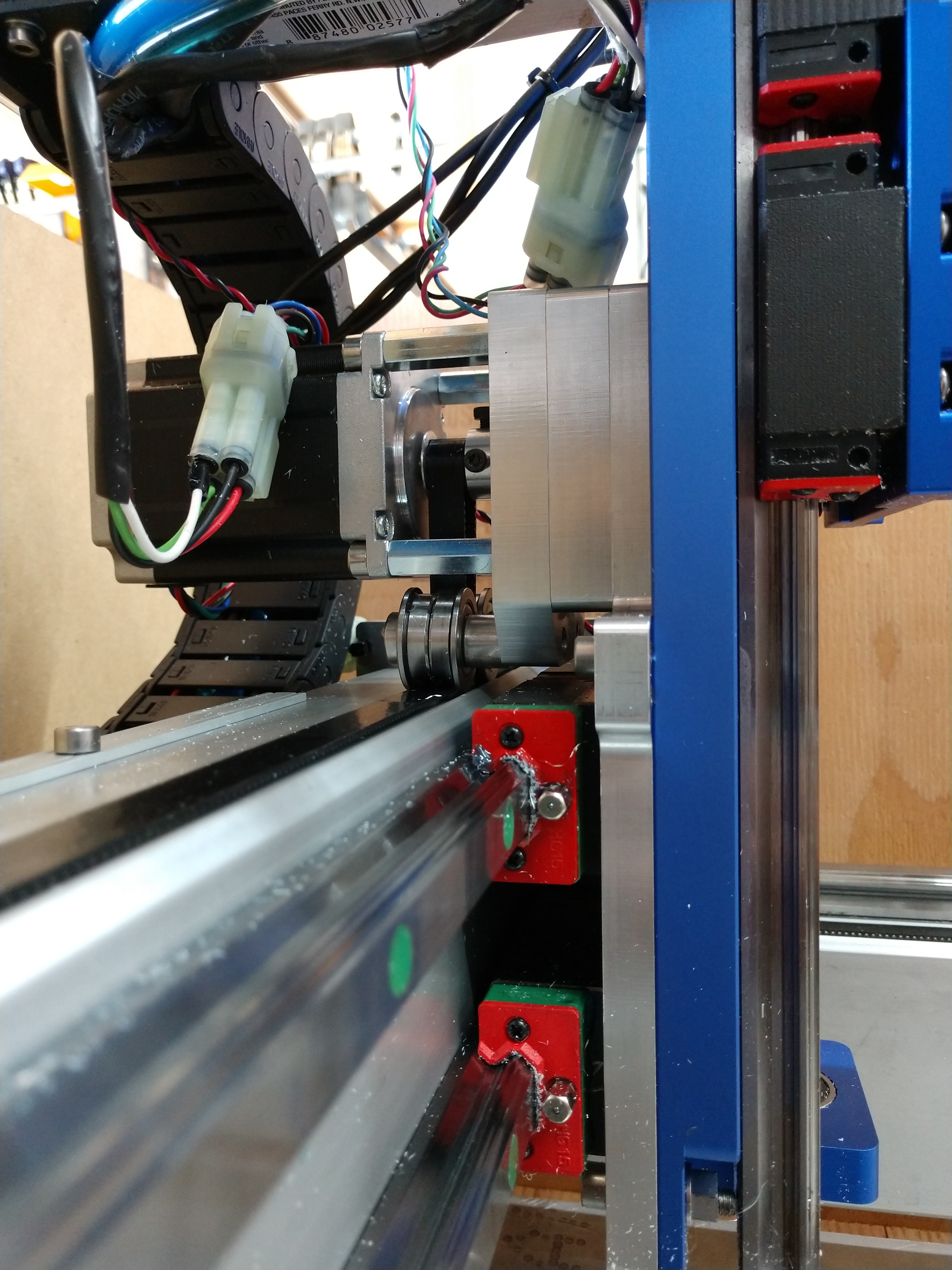
There hasn’t been much attention on the X-Axis, mainly because I was working on fixes from the rush job.
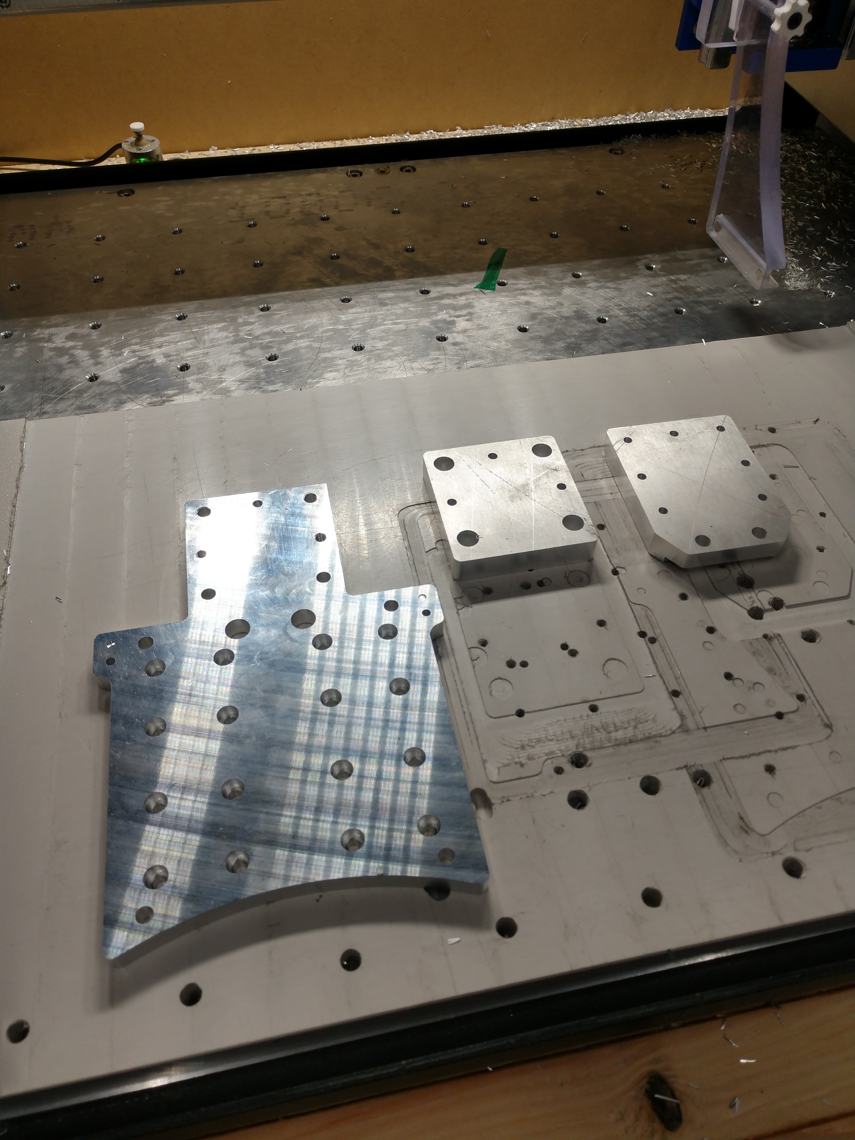
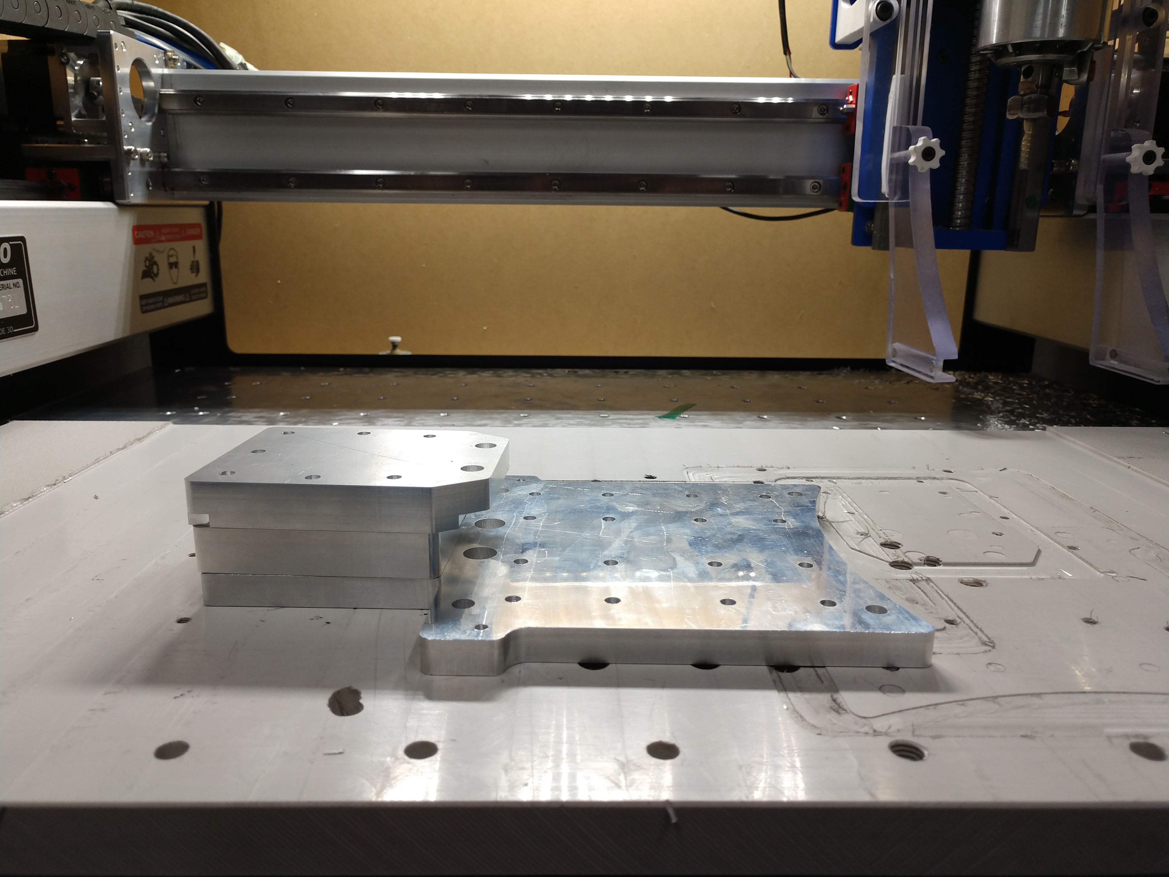
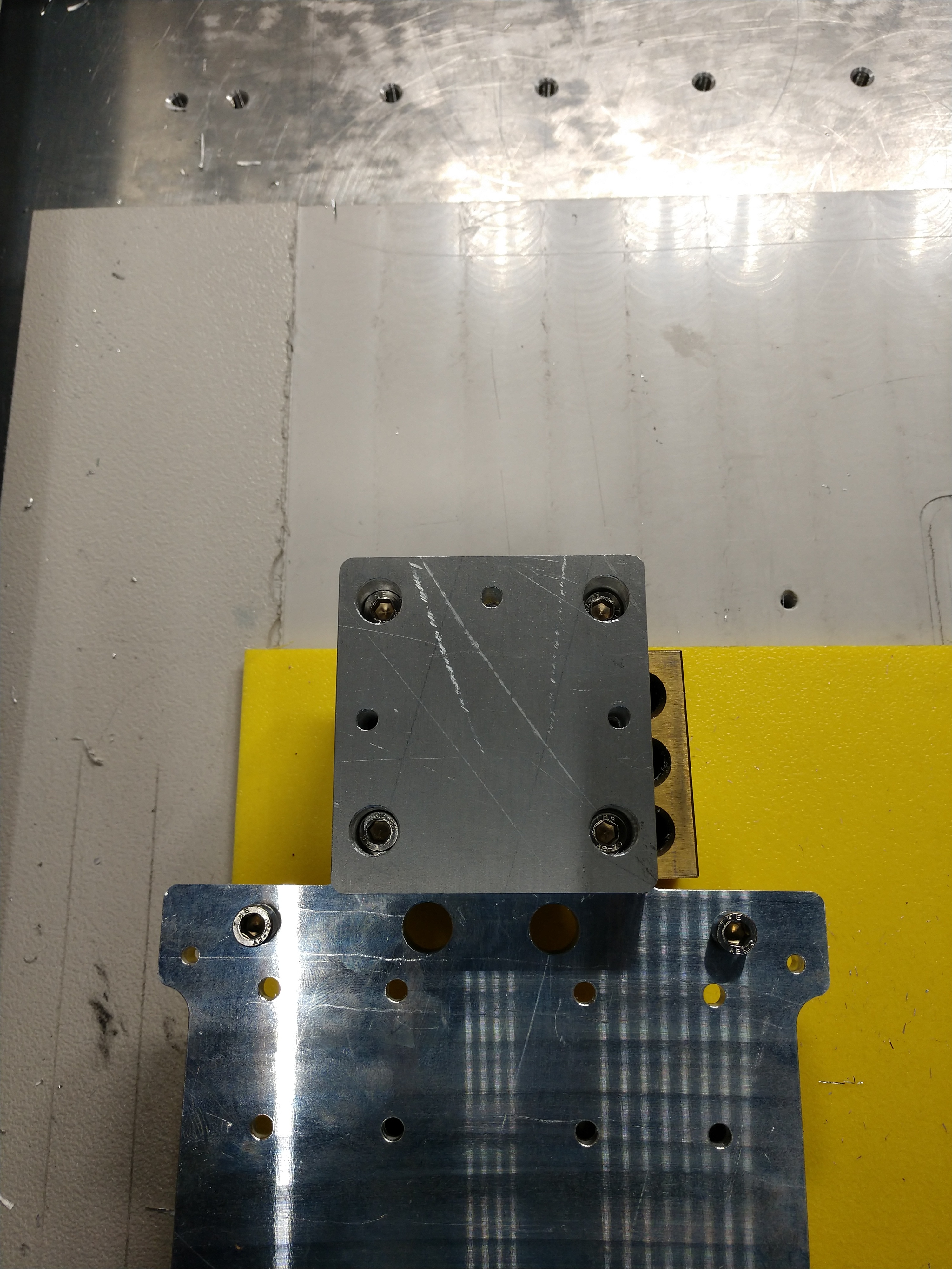
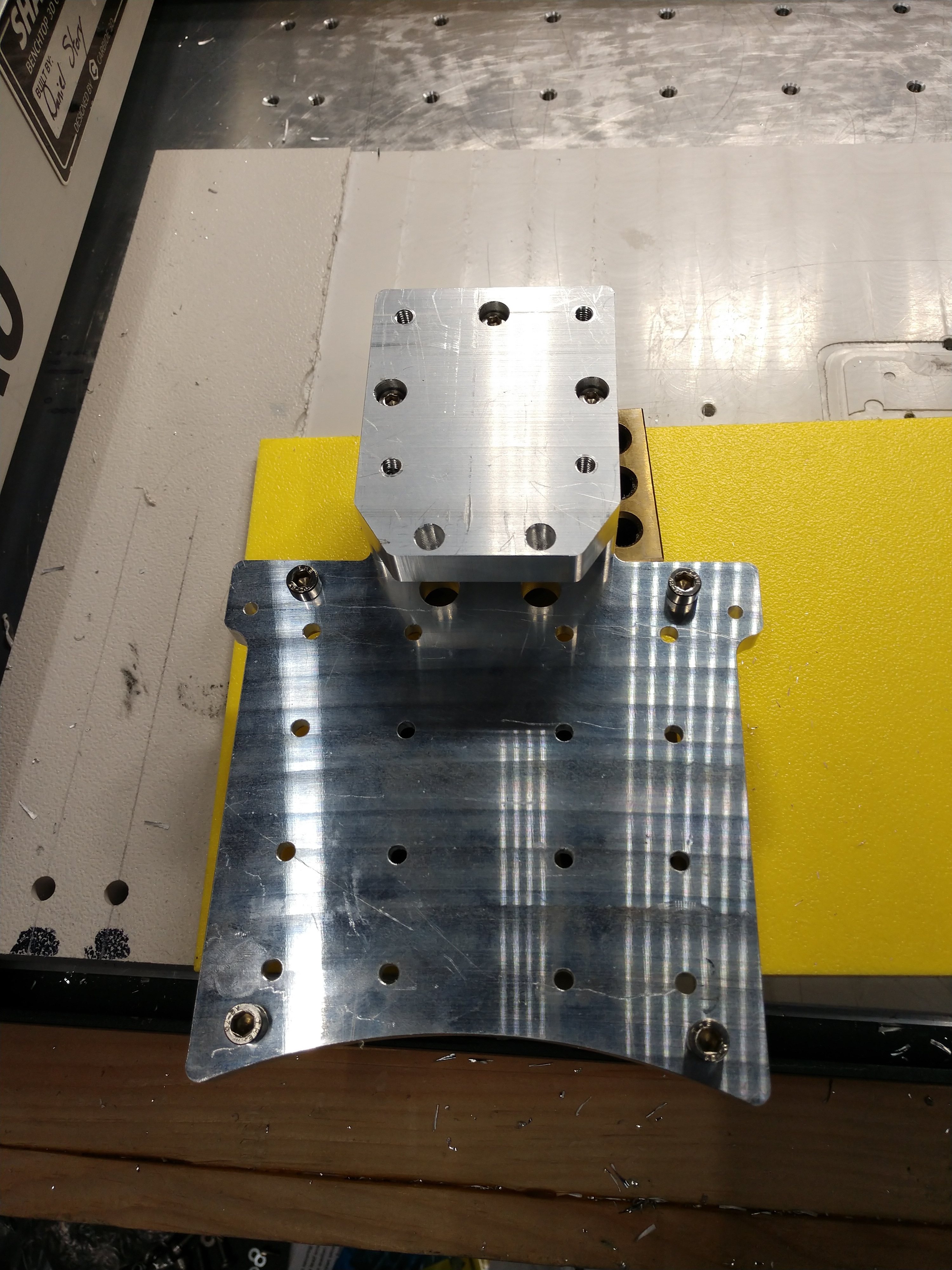
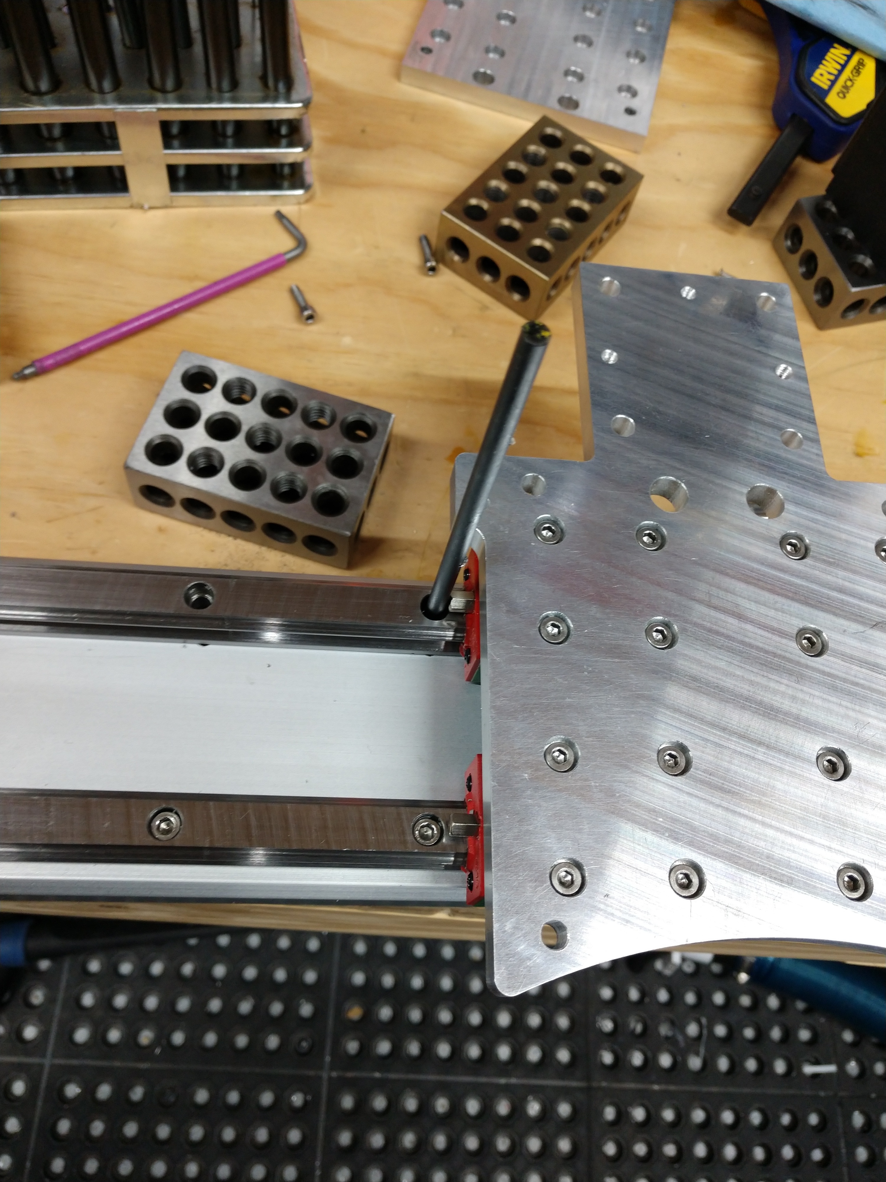
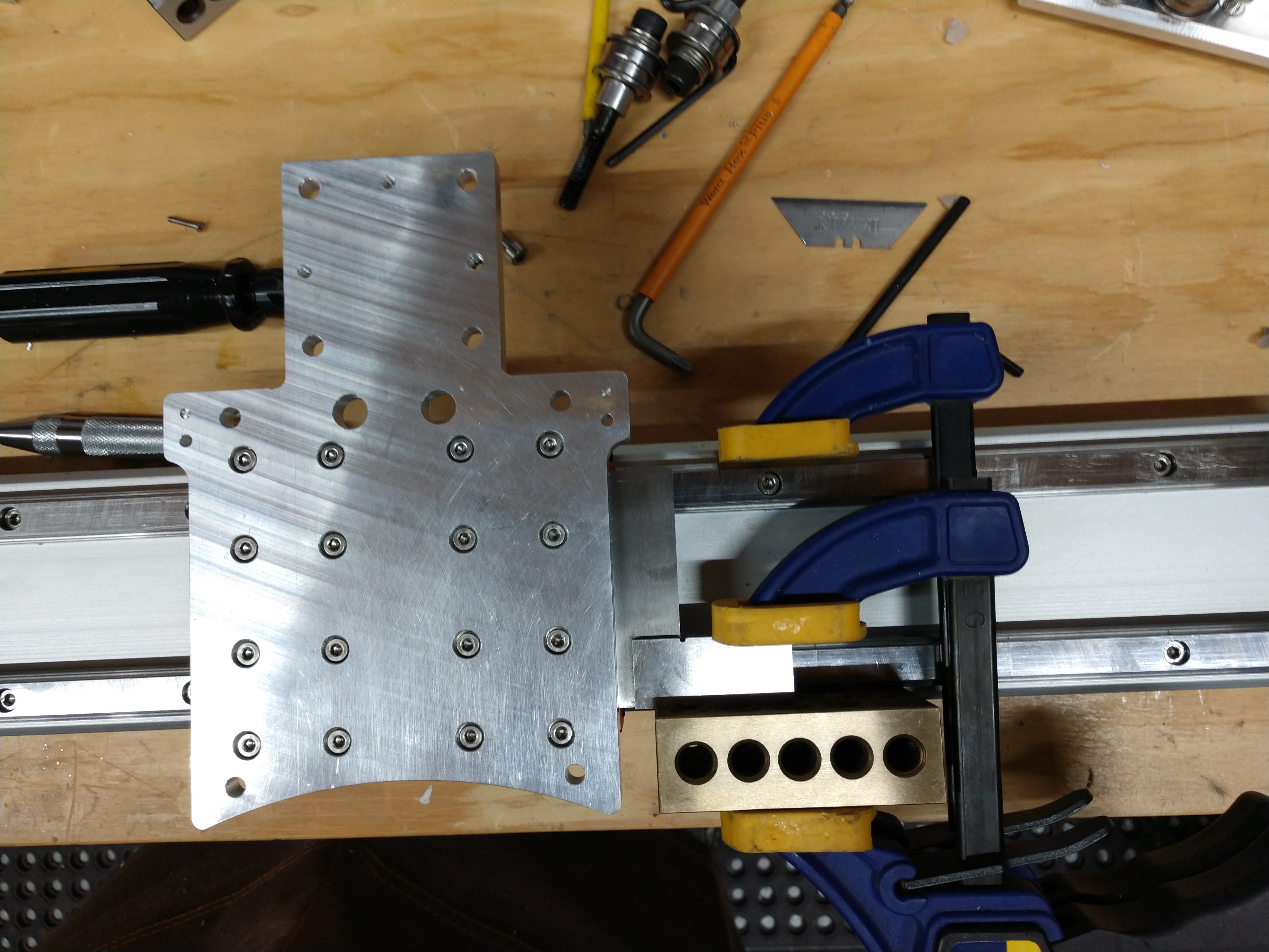
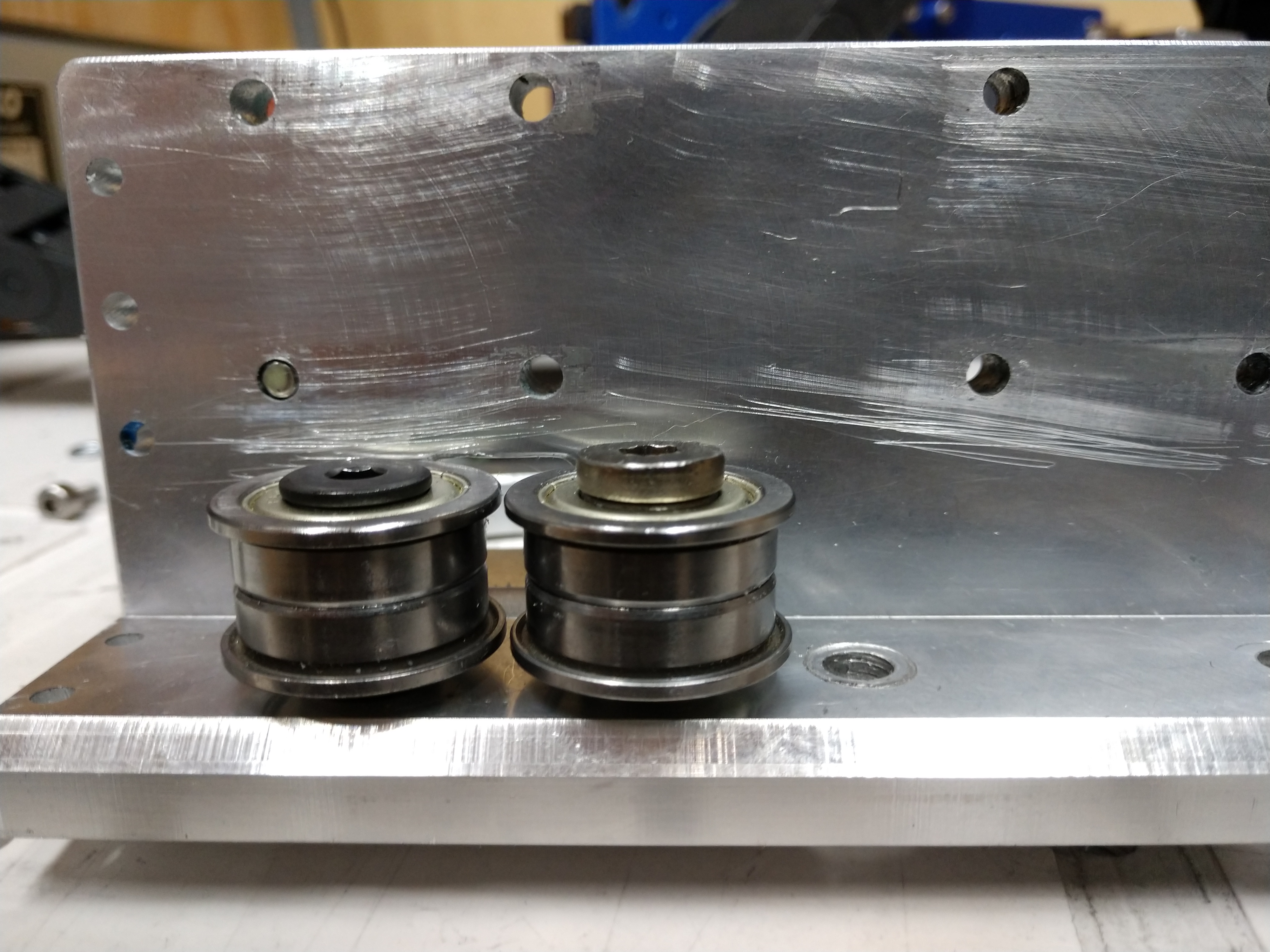
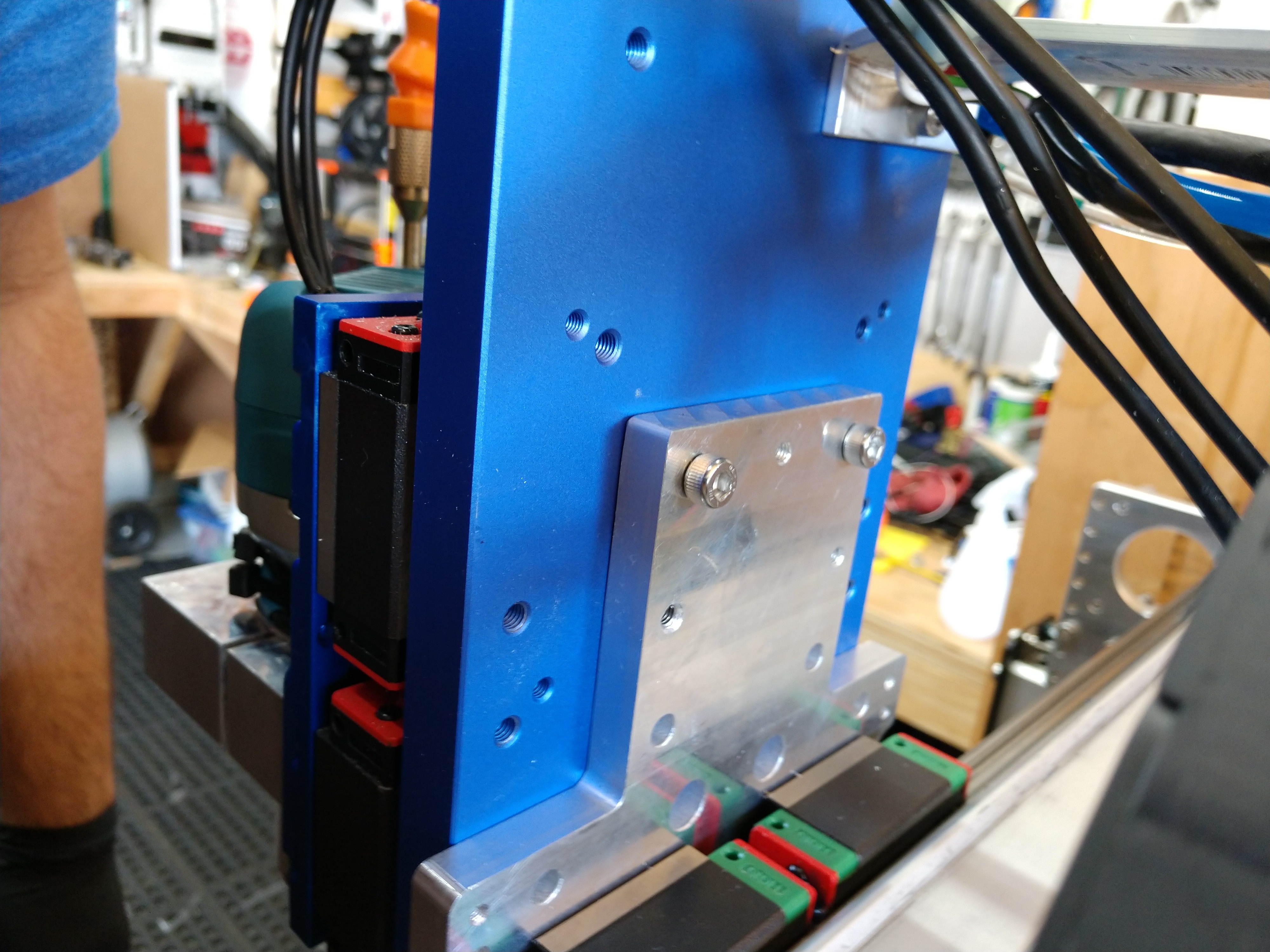
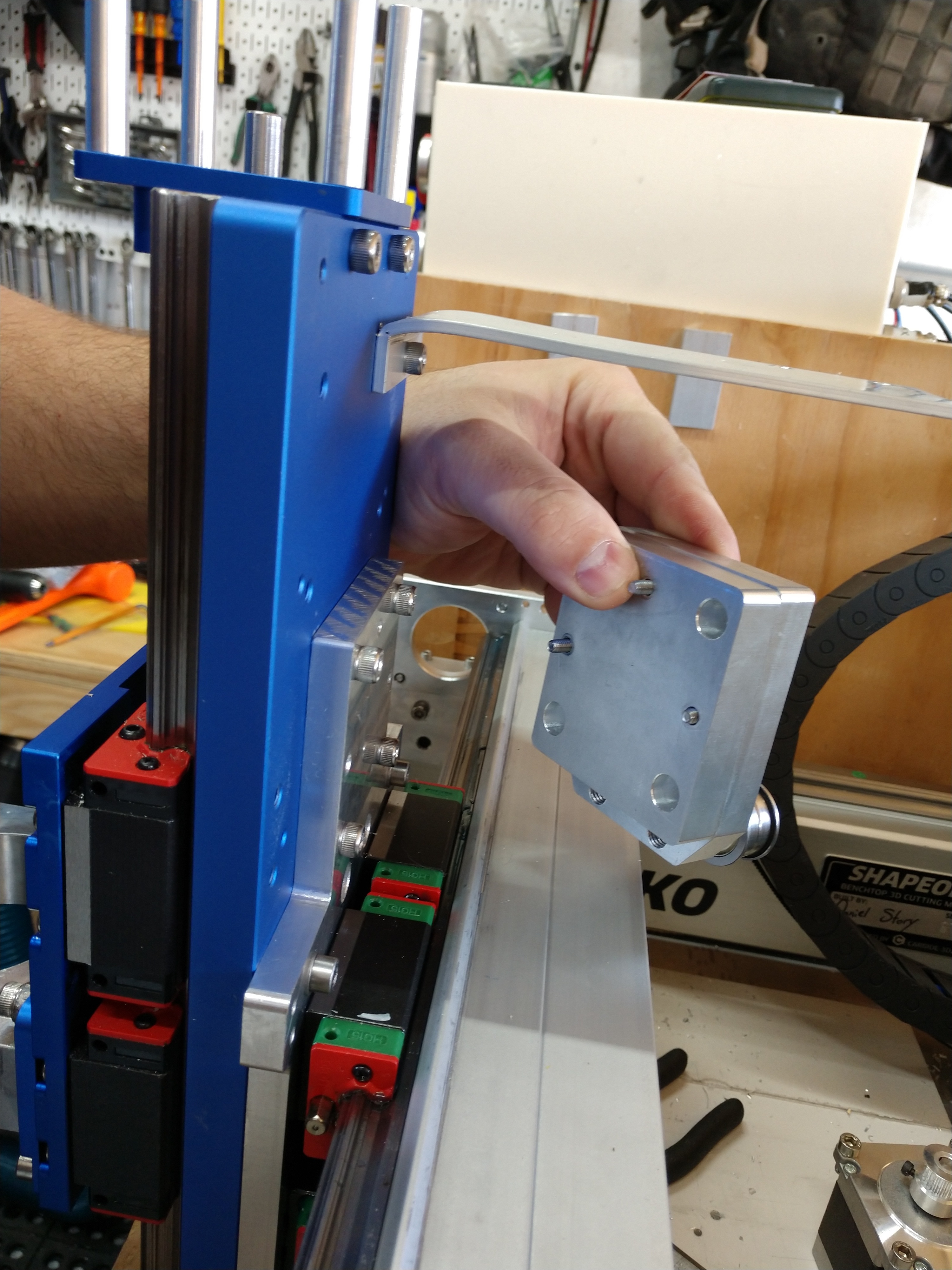
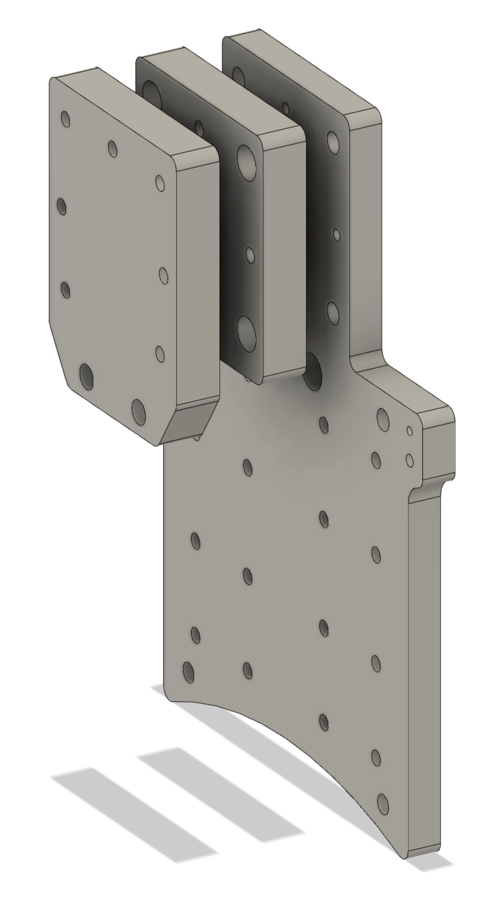
I pretty much redesigned the whole X adapter plate at this point, originally it was fairly simple rectangle piece with a large block to act as a spacer for the stepper motor and belt idlers, as I milled it manually. I never actually milled the spacer block out of aluminum and just continued to use my 3D print prototype with temporary (oversized) hardware.


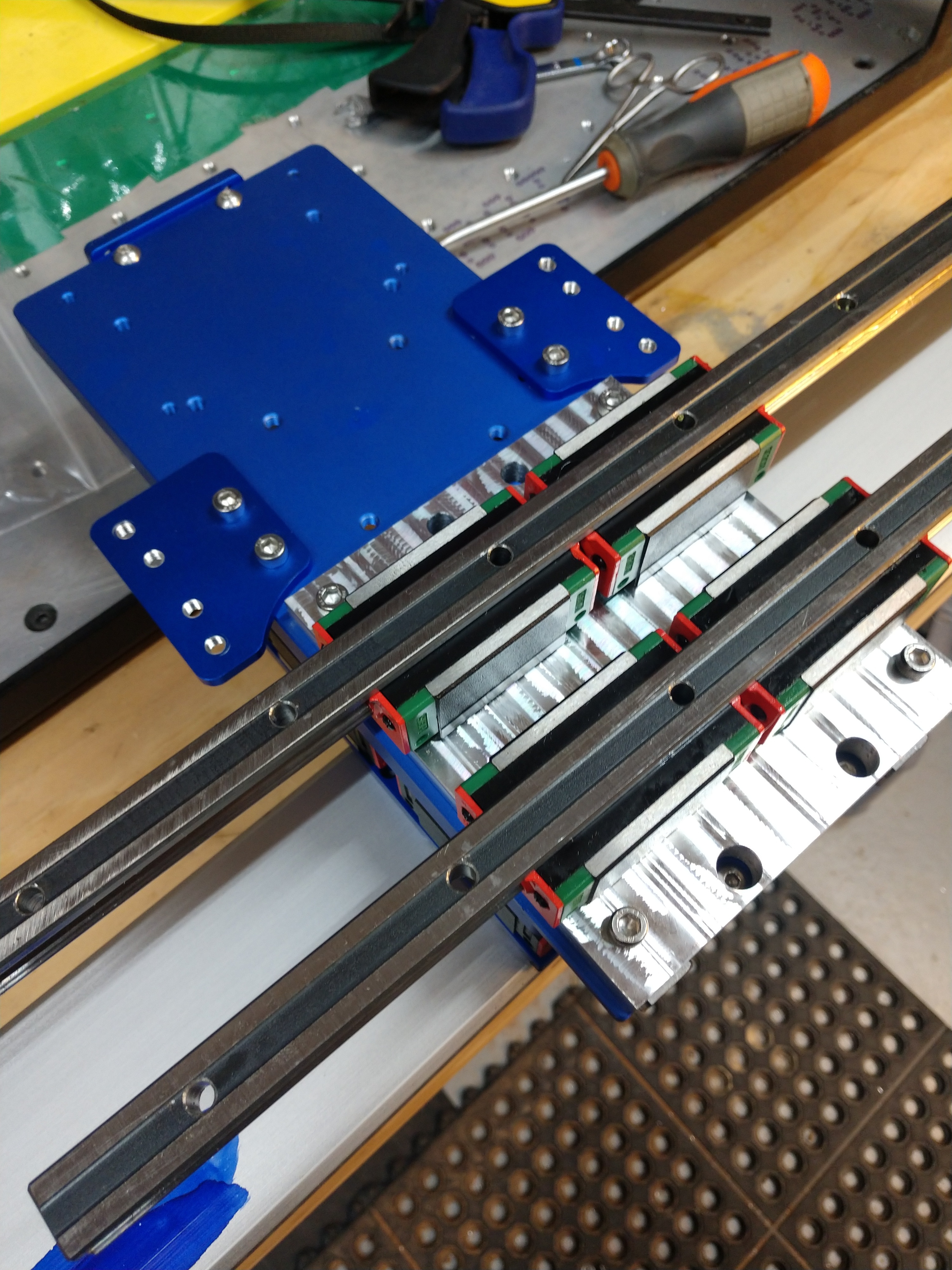
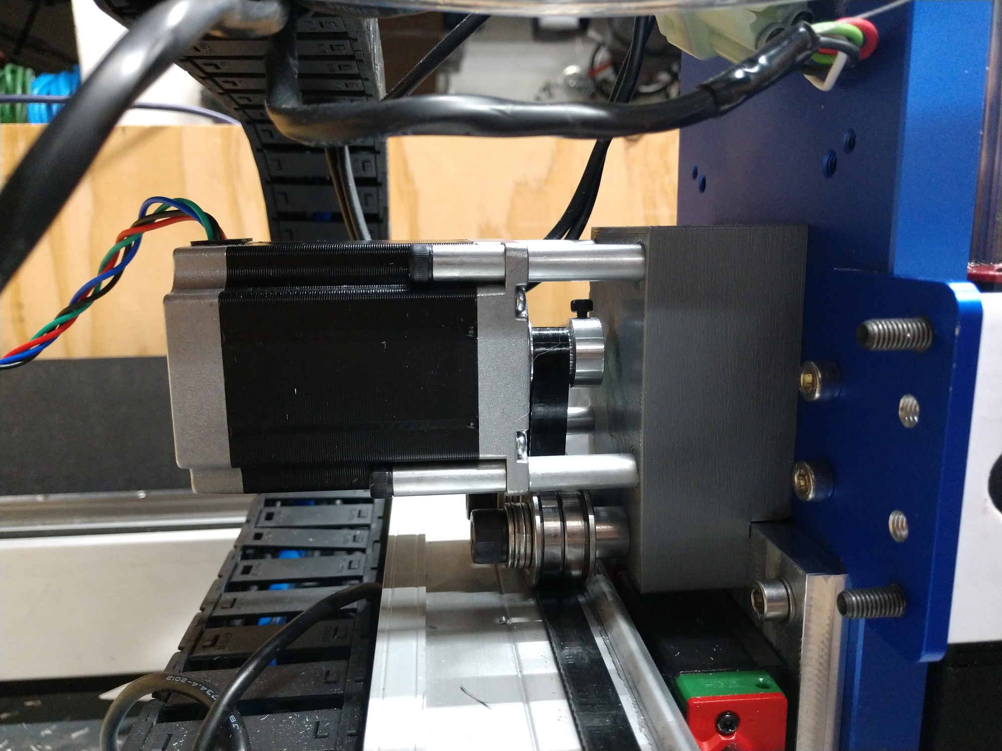
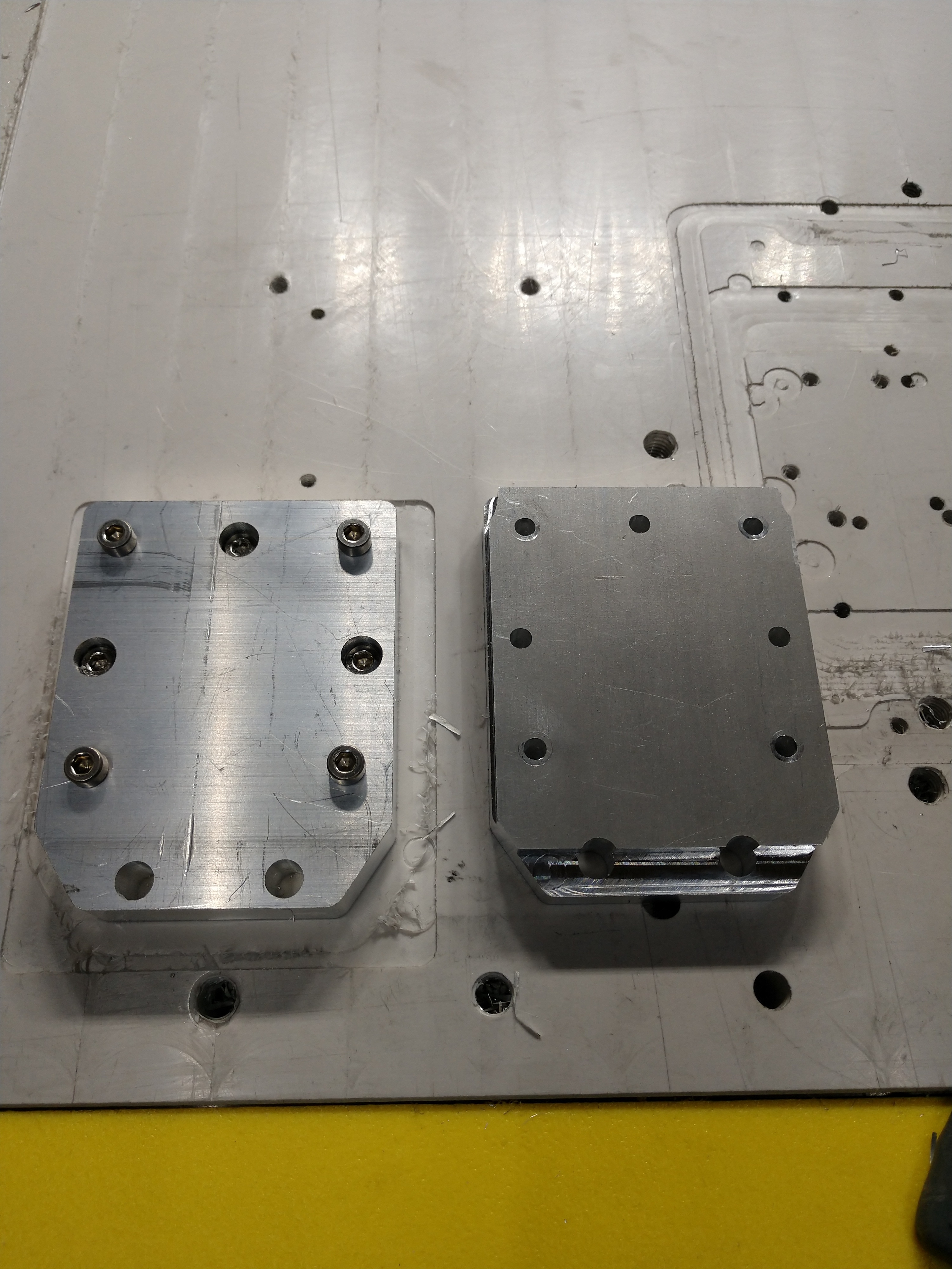
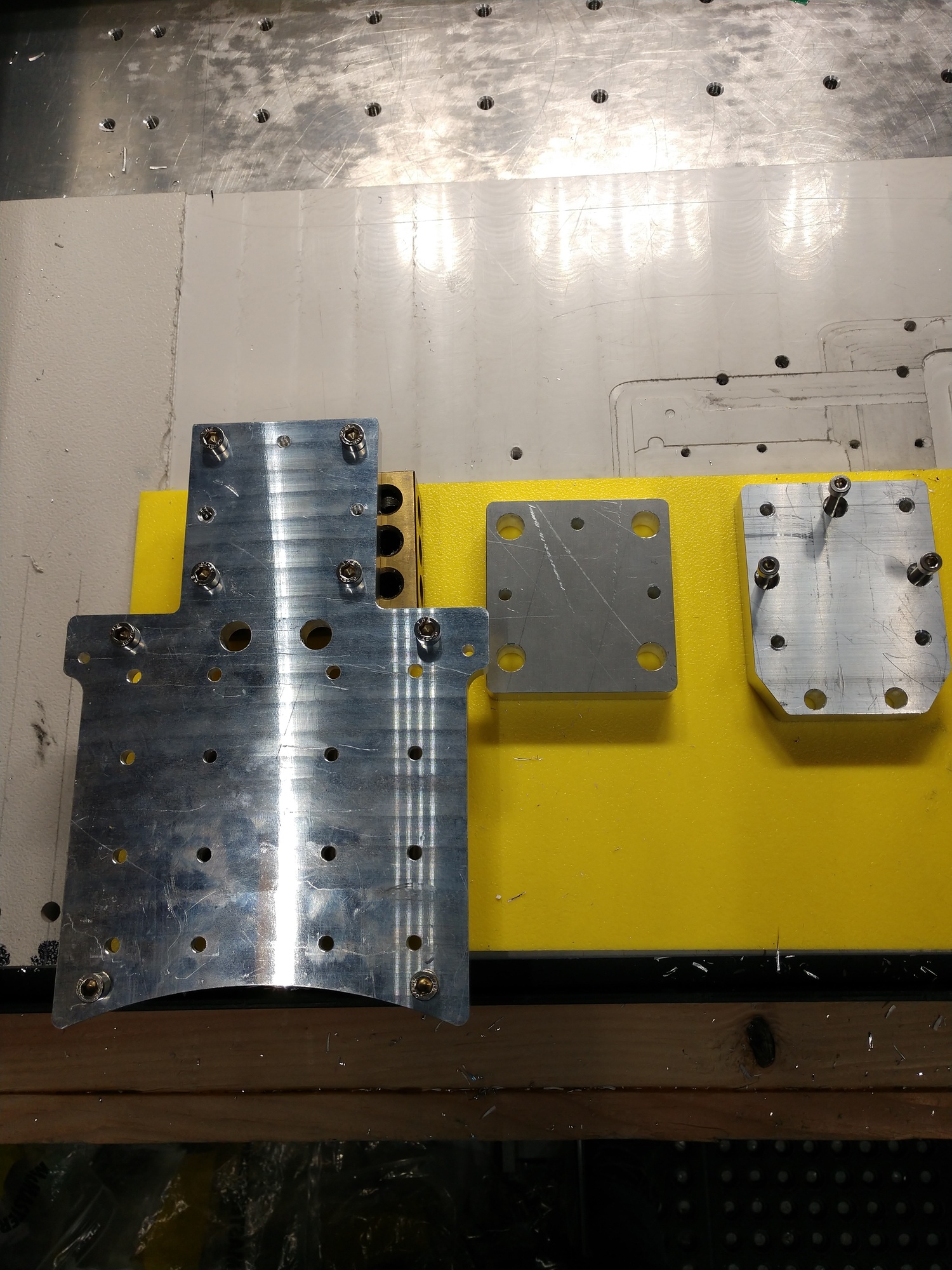
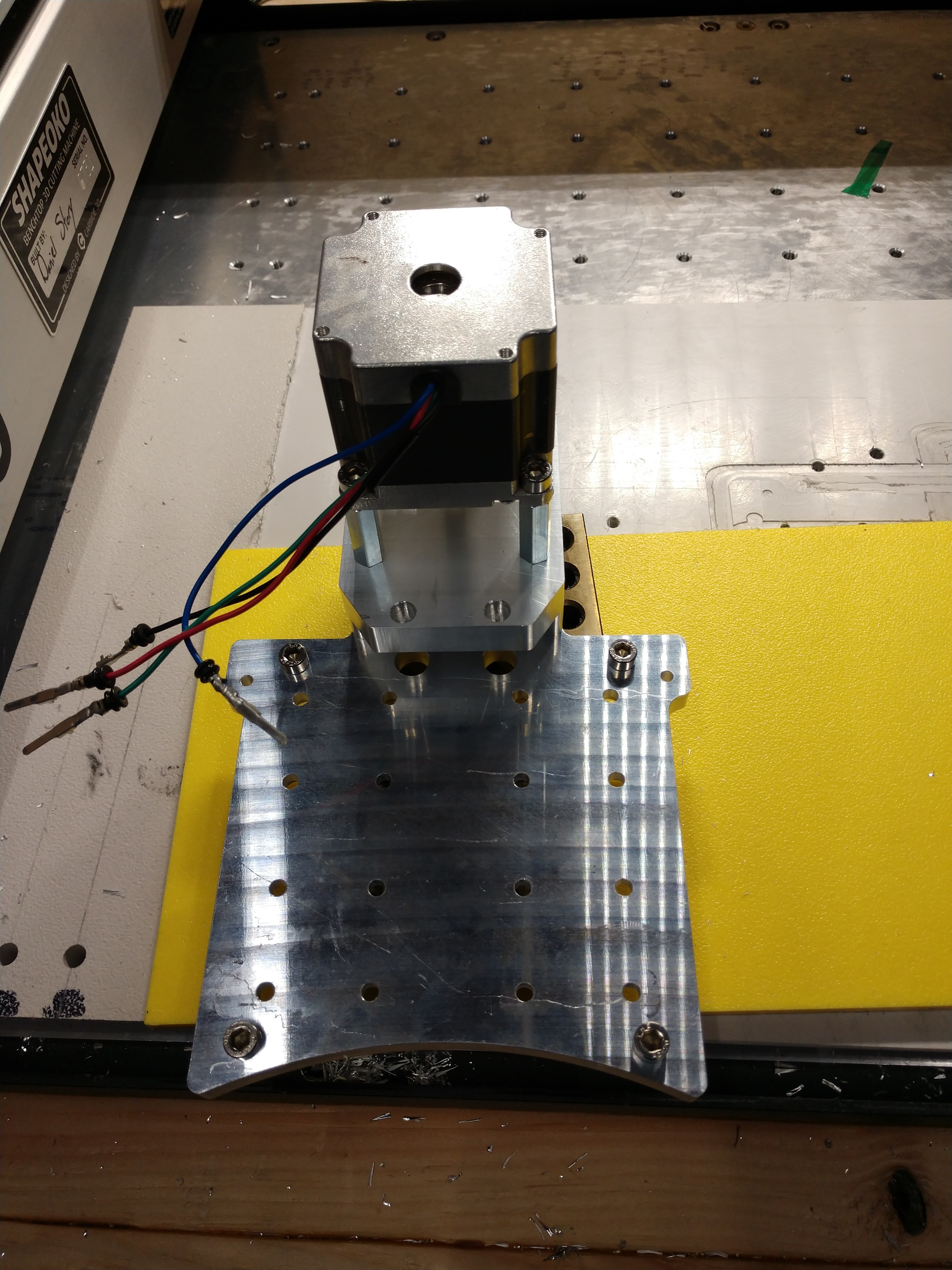
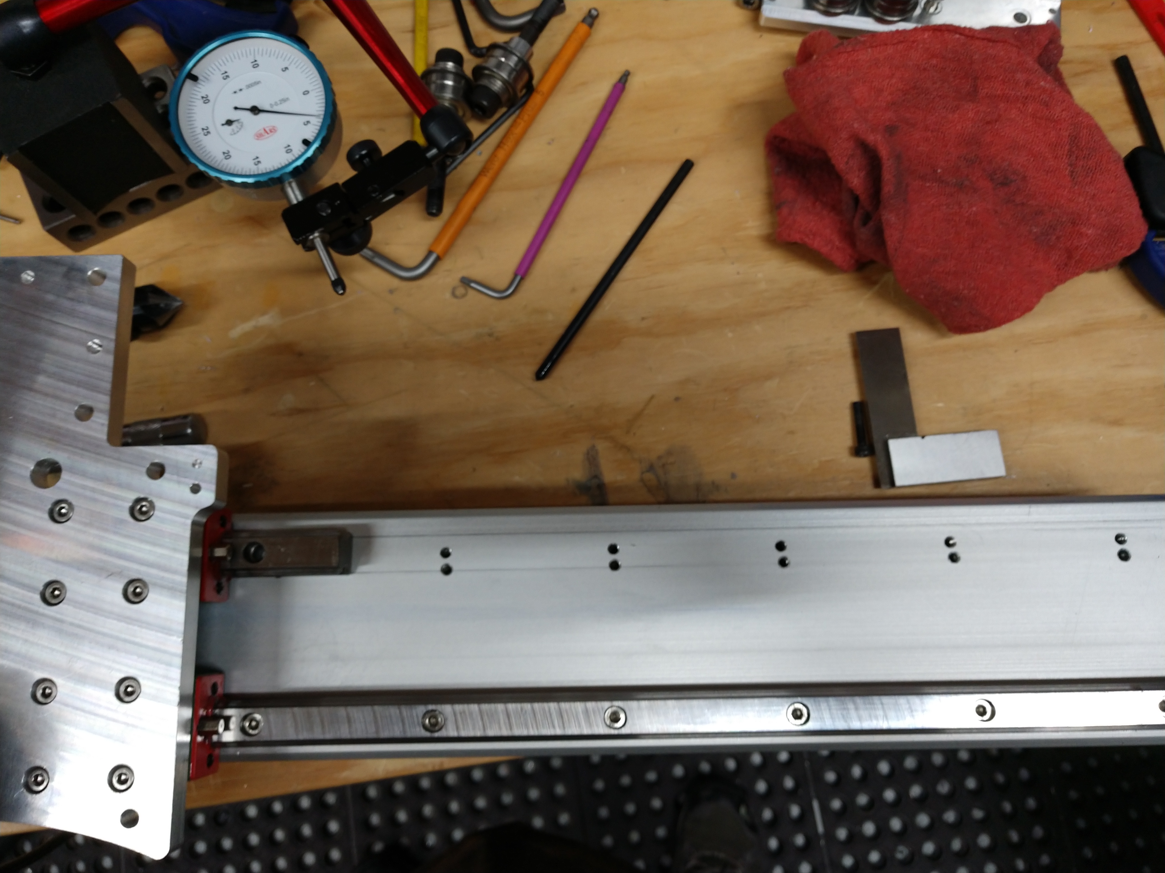
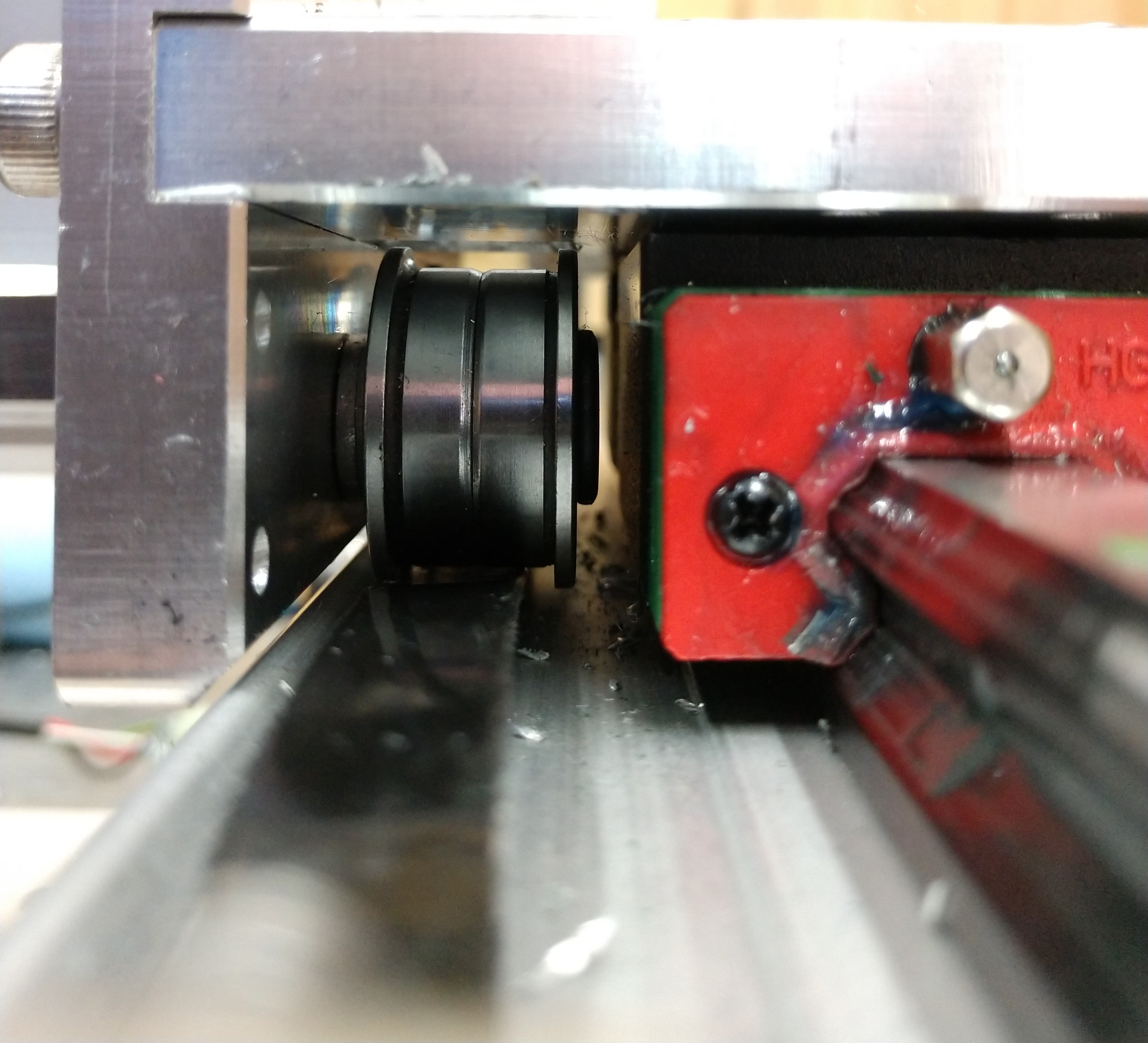
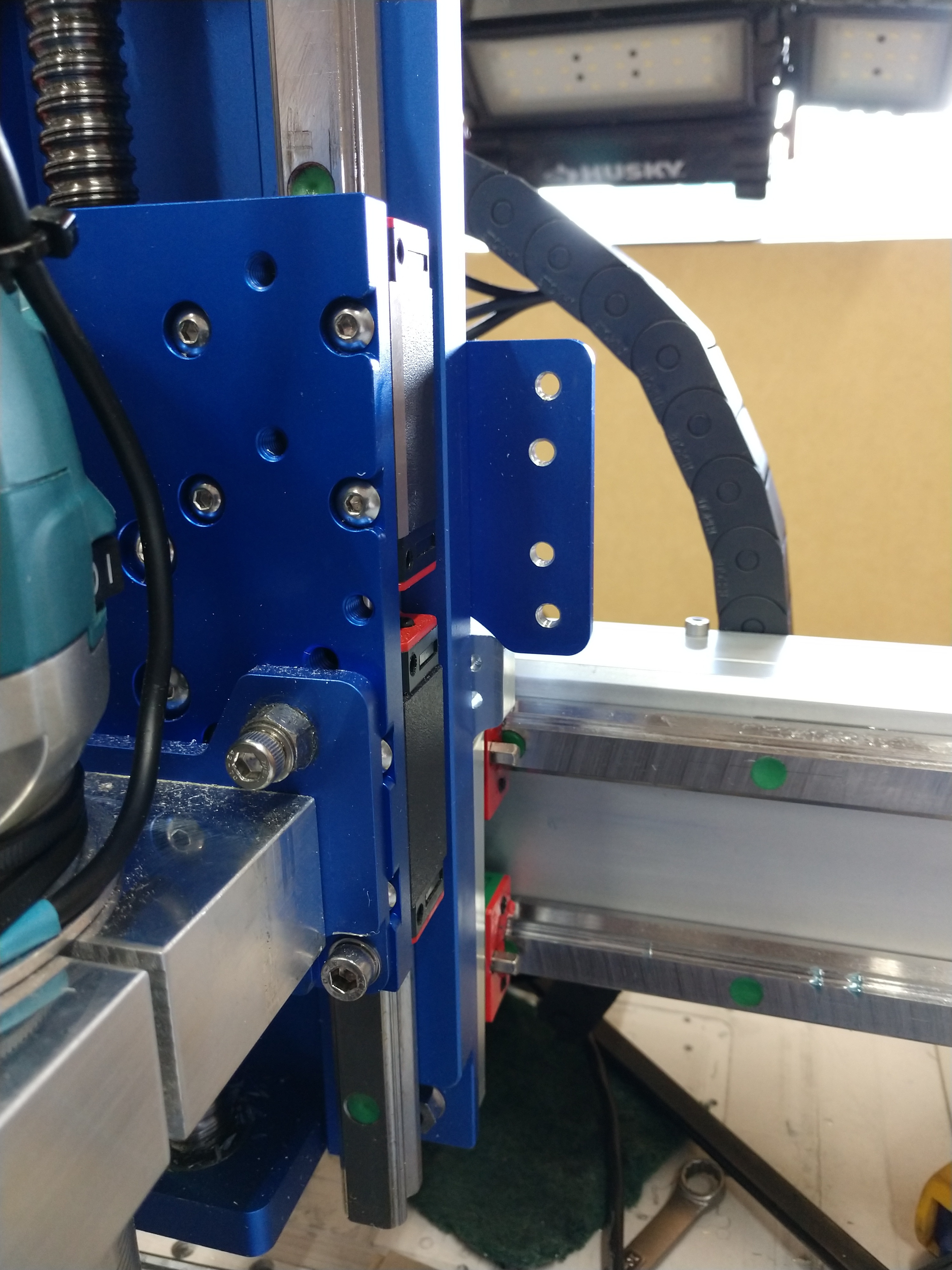
From the design flaws of that first attempt and seeing other people’s implementations; I widen the stance of the two rails, added bumpers that act as mounting point for limit switch(es) and protecting the bearing blocks from colliding with the Y-Axis plates. I also reduced additional hardware required by redesigning the motor spacer and mounting.


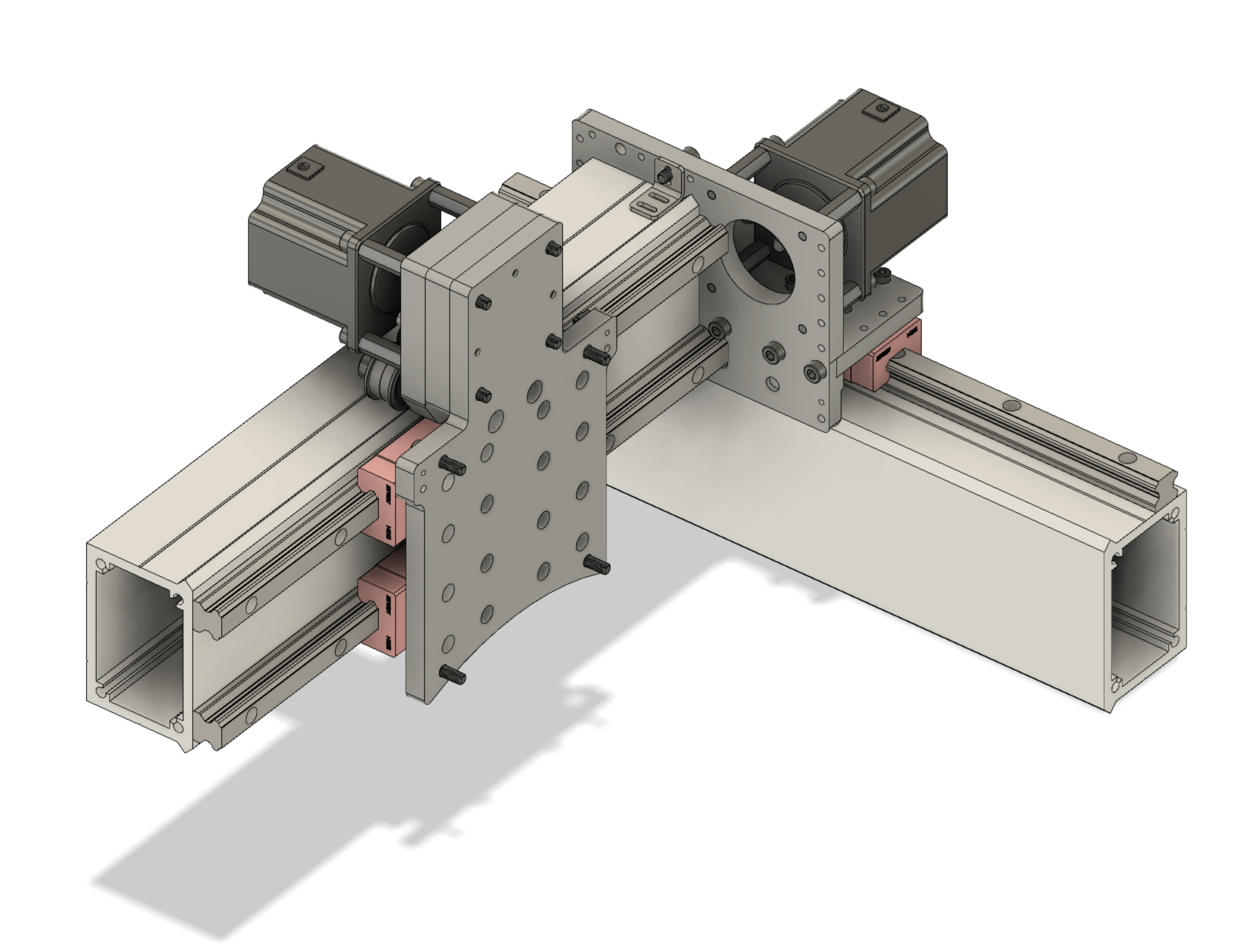
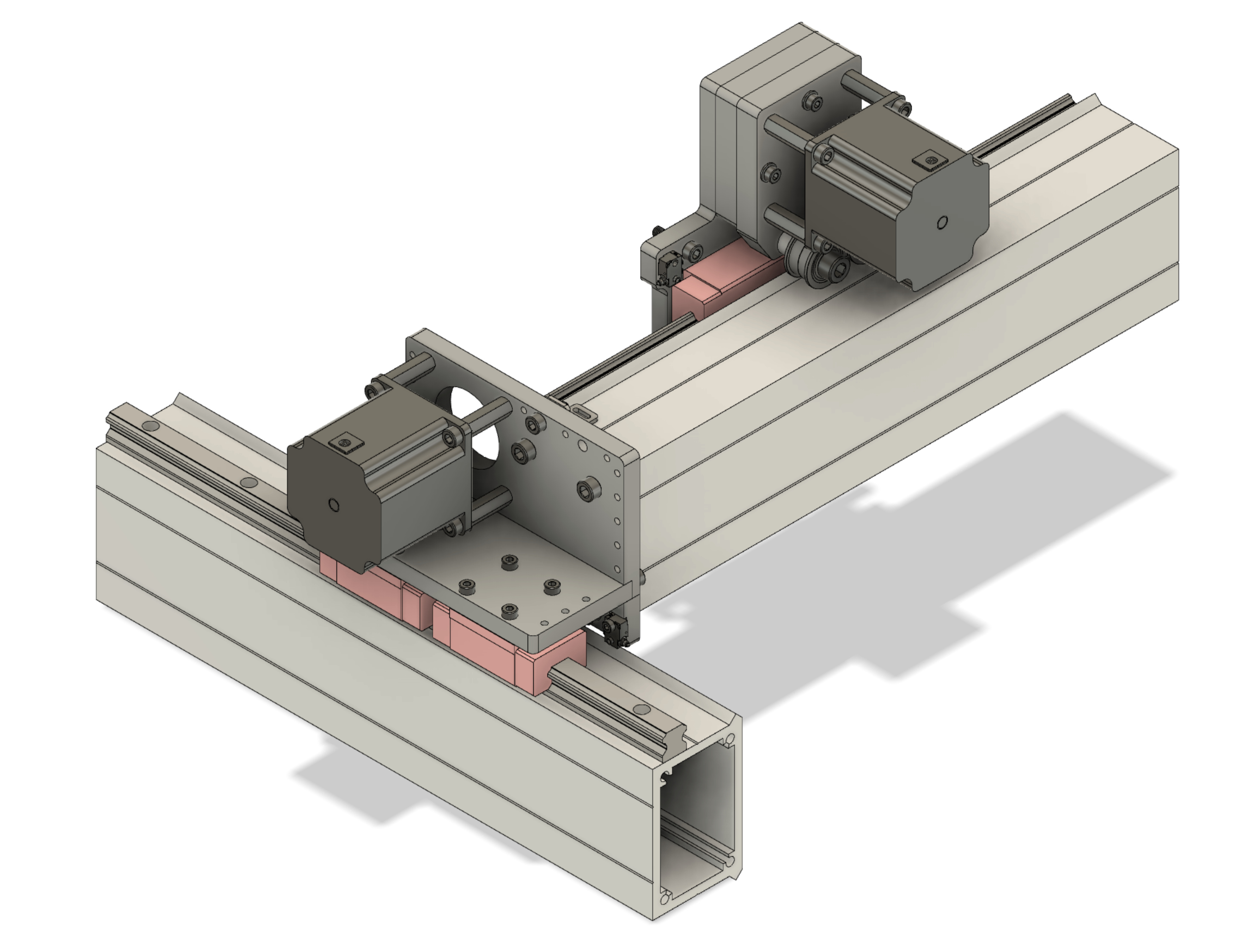
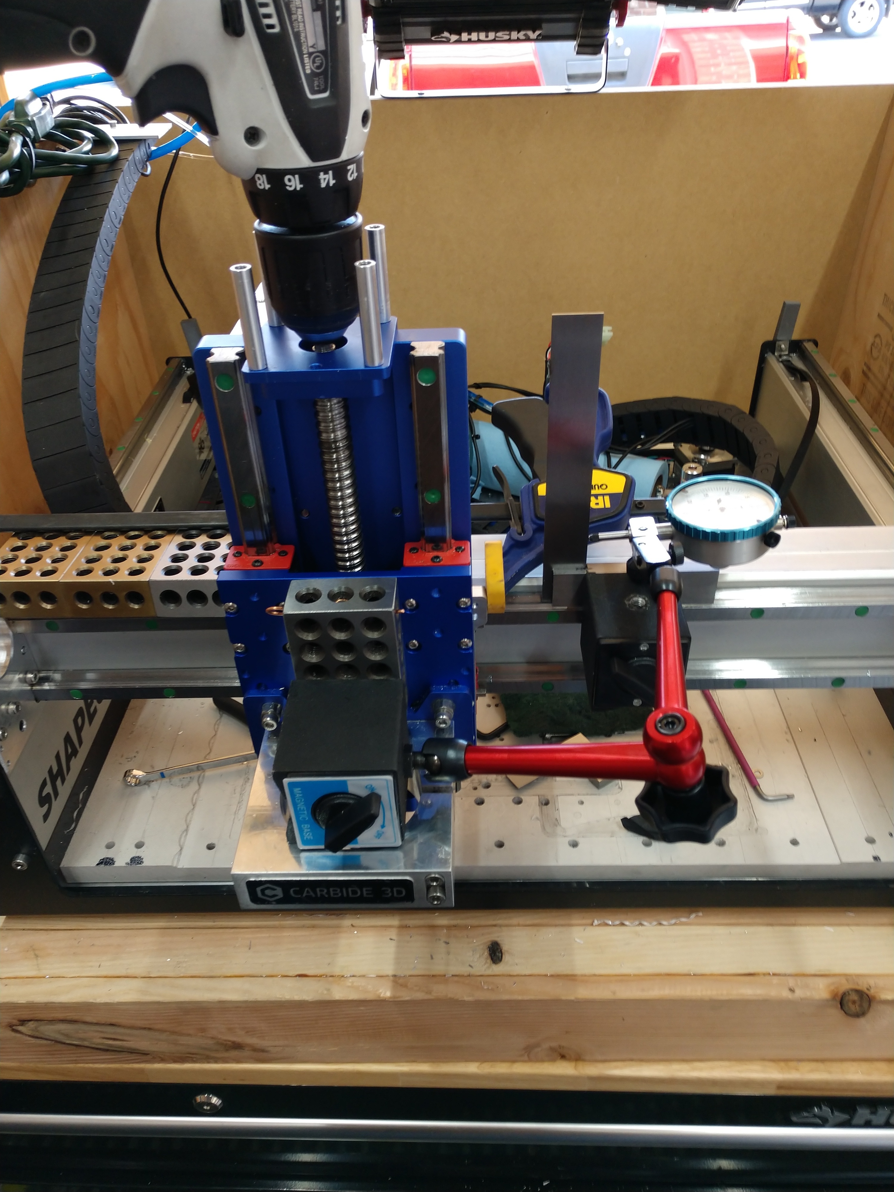
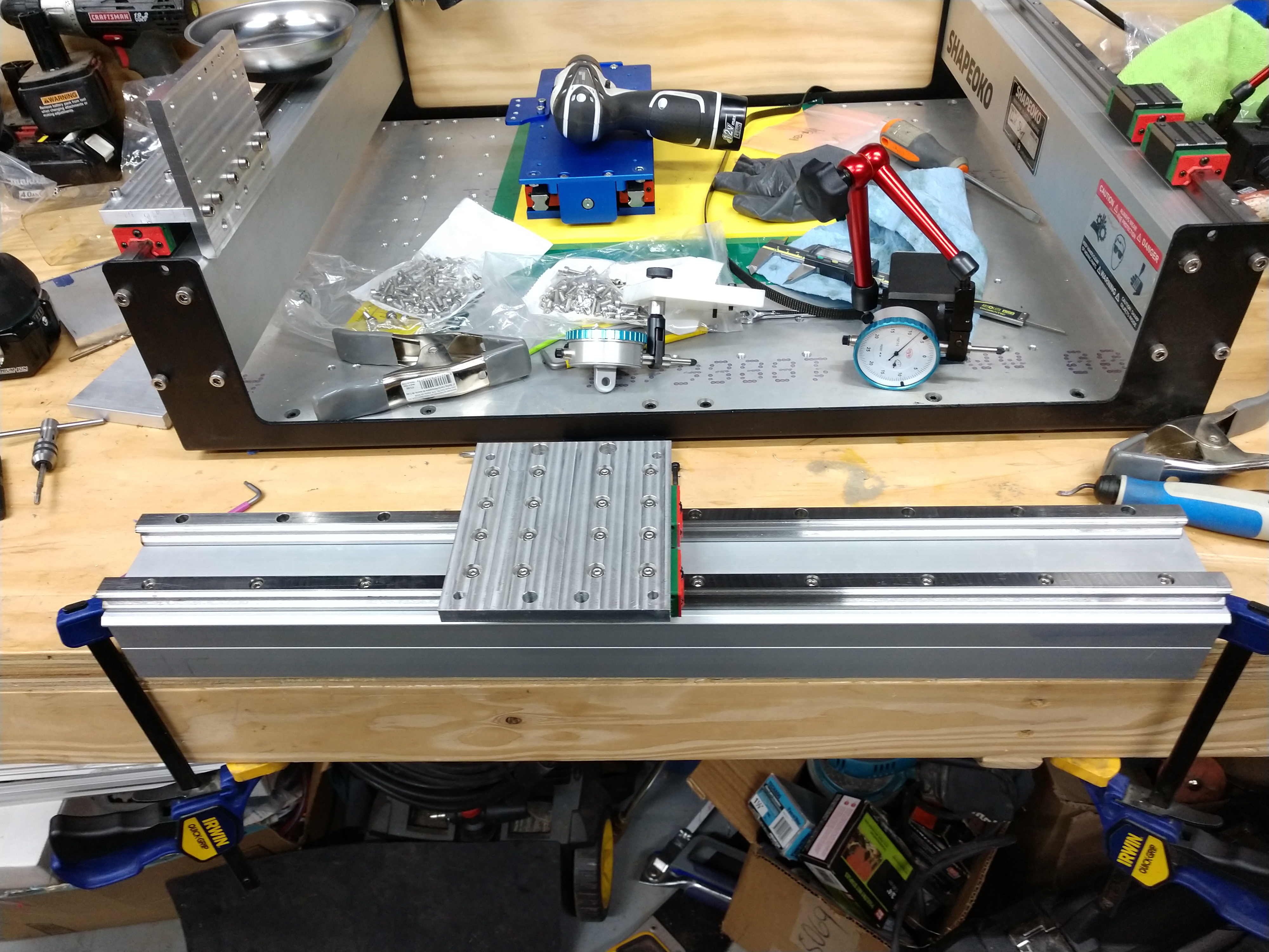
The design has not been verified yet, I am working on milling them out today, and reassembly tomorrow. I will have to remount the linear rails due to the wider stance but it will be better in the end.

10 Likes

Very much enjoying this thread. I would love to do this.

1 Like

Just checked your instagram … very impressive work.

May I ask what is the green tape that you use to hold down the Aluminum? Seems to hold on great. Havent found anything like it.

Also, seems you using 1 flute cutter. What is the advantage vs 3 or 4 flute … do you run them faster? Slower, … ?

Sorry for the questions but I am learning and you seem to know your stuff!

Thanks.

1 Like

NYC CNC popularized the tape+glue method, originally using blue masking tape. They since evolved to using “Power Coating” tape (aka Polyester [PET]
tape), that they mention in one of their videos. It is less susceptible to liquids (i.e mist coolant) and heat

Winston breaks it down best on Machining Aluminum with the 278-Z on the Shapeoko

1 Like

What can I say, I’m a day behind :slight_smile:

Finished milling the parts, made a human error on the last one but it is still functional. Accidentally had the wrong g-code loaded, what happens when they look so similar and are named too similar :stuck_out_tongue:

I am using ATP-5 for the adapter plate this time, want to verify if I can get away with its flatness spec instead of having to manually mill 6061 for flatness and parallelism.
Just waiting on some longer M4 screws than the ones I have at hand, but should be about it.


8 Likes

Dan, great, thanks for getting back to me. Super!

1 Like

I think you mean “powder coating tape” as it’s often used to mask for powder coating. It uses a silicone PSA that resists alcohols much better than the rubber-based PSAs used in masking tapes.

5 Likes

Ended up remaking that last part, the motor mount. I added some counterbores so I could use hardware on hand too.

To show the gist of assembly, you would attach the the HDZ via M5 screws where the V-Wheels used to be, plus now also the original x-axis stepper mounting location.

Next you place the spacer on (loose), it has clearance holes for the M5 screw heads from the previous step, plus three M4 clearance holes for the mounting the spacer and motor mount onto the adapter plate in the next step.

You’d then place the motor mount on top, and mount with 3 M4 screws. You also mount the OEM belt idler pulleys in the lower M8 threaded holes (not shown cause they are still on my Shapeoko ;-))

And lastly mount the stepper motor.

Now I just need to remount the linear rails to the new spacing spec and make sure everything fits and clearances met. Once I verify this I’ll upload these additional designs to Thingiverse along with the other CAD sharing sites mentioned before to complete the project.

10 Likes

To get the new x-axis plate on, I have to remove the whole extrusion which isn’t necessarily the easiest task, especially when you have limited space. This is why it is always good to design an enclosure where you have easy access on all sides :wink:

To get to the two bottom screws for the extrusion, it requires removing the carriage block. Who designed this thing!? :stuck_out_tongue:

After removing the top rail, I measured my bottom one. It was 0.16mm off, which is close enough. Otherwise I would have had use the other side to remount both rails.

Lazy is as Lazy does. I used the adapter plate to adjust and mark the mounting holes for the top rail with a transfer punch. Just make sure your rails (via carriage blocks) are parallel! Pretty sure this method violates a lot of rules :wink:


Just checking my plate is square with the rail before remounting the extrusion back on the SO3.

Remember how I had clerance issues with the Y-axis belt idler screw and carriage block? Yeah, when I completely redid the assembly design, I noticed the idler pulley in the SO3 CAD file was the wrong size. This was an older SO3 with the 6mm(?) belts, so the pulley wasn’t as wide. Updating the part, I clearly saw I had clearance issues. I have been using low profile M8 screws and milling their heads down to add additional clearance as the ultra-low profile screws are fairly pricy, it would double my materials cost. I have since found a better source for ultra-low M8 screws, without having to do additional modifications.


Look at that, there are MILES of room now!

I used the two top motor holes to loosely hold the HDZ


I did have one design issue, those pesky suck-it ears, they don’t clear the bumpers on the adapter plate. I’ve since added more radius to those bumpers in the design which should resolve this.

I then square the HDZ’s Z travel to the rail as well, using the v-wheel eccentric nuts for adjustment.

Lastly the motor spacer and mount stack on top of the X-axis adapter.


I have some video of the new setup cutting on my instagram:

Finally, I have updated my Thingiverse design with the X-axis plate (it’s also on GrabCAD now), so go get yours today! :slight_smile:

10 Likes

must…resist…the urge

7 Likes

Get in there it’s sooo awesome :sunglasses:

2 Likes

If I do it I’d have to replace the belts with screws too. Way too much to contemplate now

1 Like

This is amazing great work. Might just have to do this. If you do not mind where did you get your rails

2 Likes

Eventually :slight_smile: For now it is adequate for me.

eBay. There are plentiful of sources out there, some that may be better than others :man_shrugging:

1 Like

Thanks. Did you have a full 3d model of your shapeoko or did you just measure everything.

2 Likes

I used an older revision of Shapeoko 3 that is floating around in the interwebs, that got me most dimensions. The HDZ I measured by hand. I never actually modeled the HDZ.

This is the furthest I did assembly in CAD, for my parts:

9 Likes

This topic was automatically closed 33 days after the last reply. New replies are no longer allowed.