Shapeoko on the Rails!

I have wanted to add linear rails to my SO3 for well over a year (I had 4x 600mm HG15 rails in a box since Nov of 2018 :stuck_out_tongue: ). I just wasn’t satisfied with the HDZ, I was getting a lot of chatter still and broke a few v-wheels when cutting into 6061. Let alone having to do such shallow DOC, really wasn’t pleasing and depending on the LOC of the endmill using only 5% or less of it. Also, what else I got to do? I’m not very artistic, so I just resort to modding my toys :laughing:

Typically, I have only ever seen people that upgrade to linear rails, go all out with ball screws as well. I didn’t really want to do that, I felt the belt drive is still efficient for my needs and at the moment only have a problem with rigidity. Nor did I want to invest in the upfront costs of both linear rails and screws all at once.

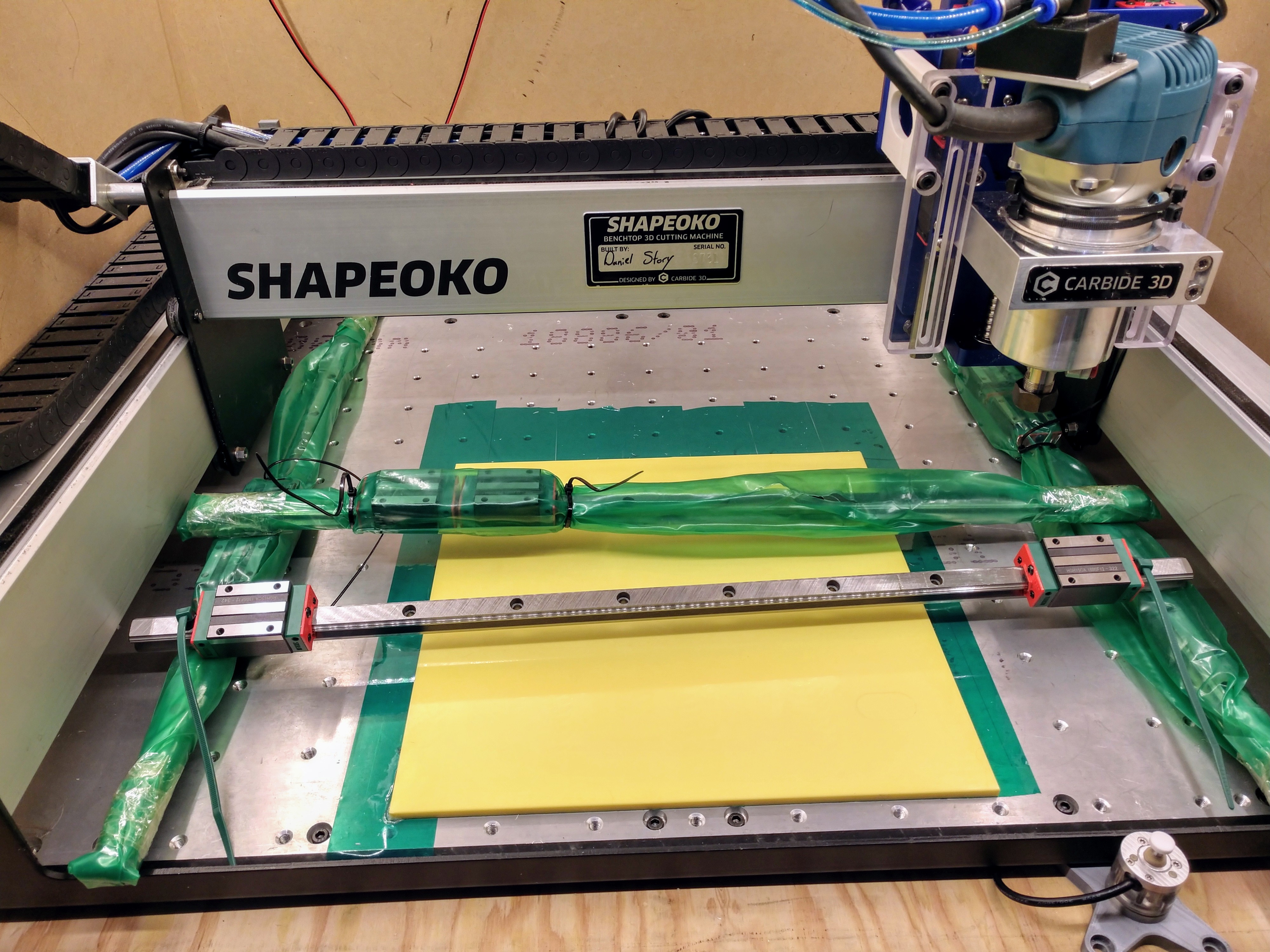
Seeing @Vince.Fab’s X-Axis linear rail mod really simplified my design in my head, originally I was going to try to mount the X rails at the top and bottom of the extrusion (this would reduce Z clearance however) but with Vince slapping the rails on the face, sacrificing some Y workspace, really made sense. I sadly wasn’t one of few that got his adapter plate :frowning:

So I ended up doing the design of the X and Y plates from scratch, copying Vince’s idea for the X plate.
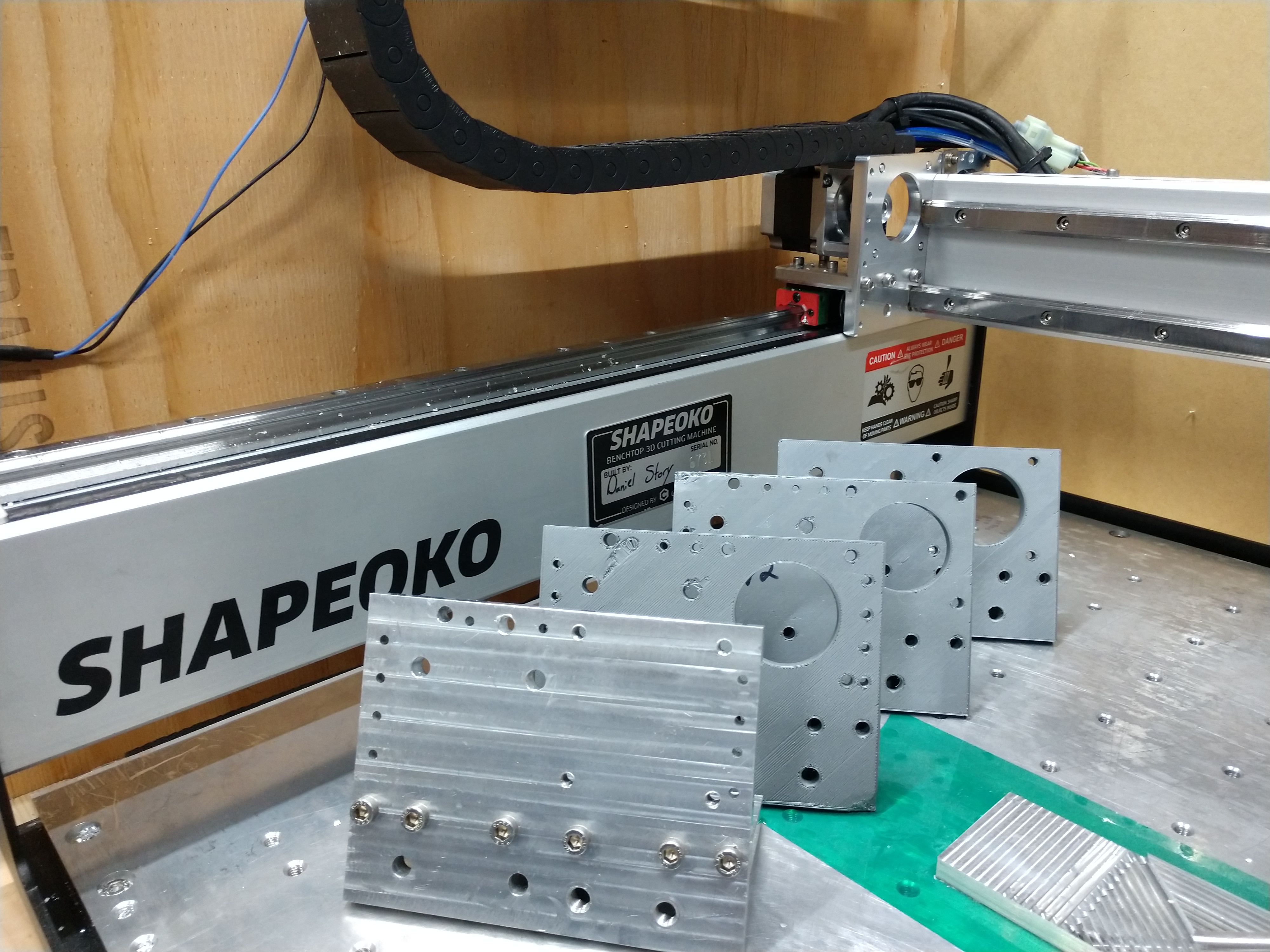
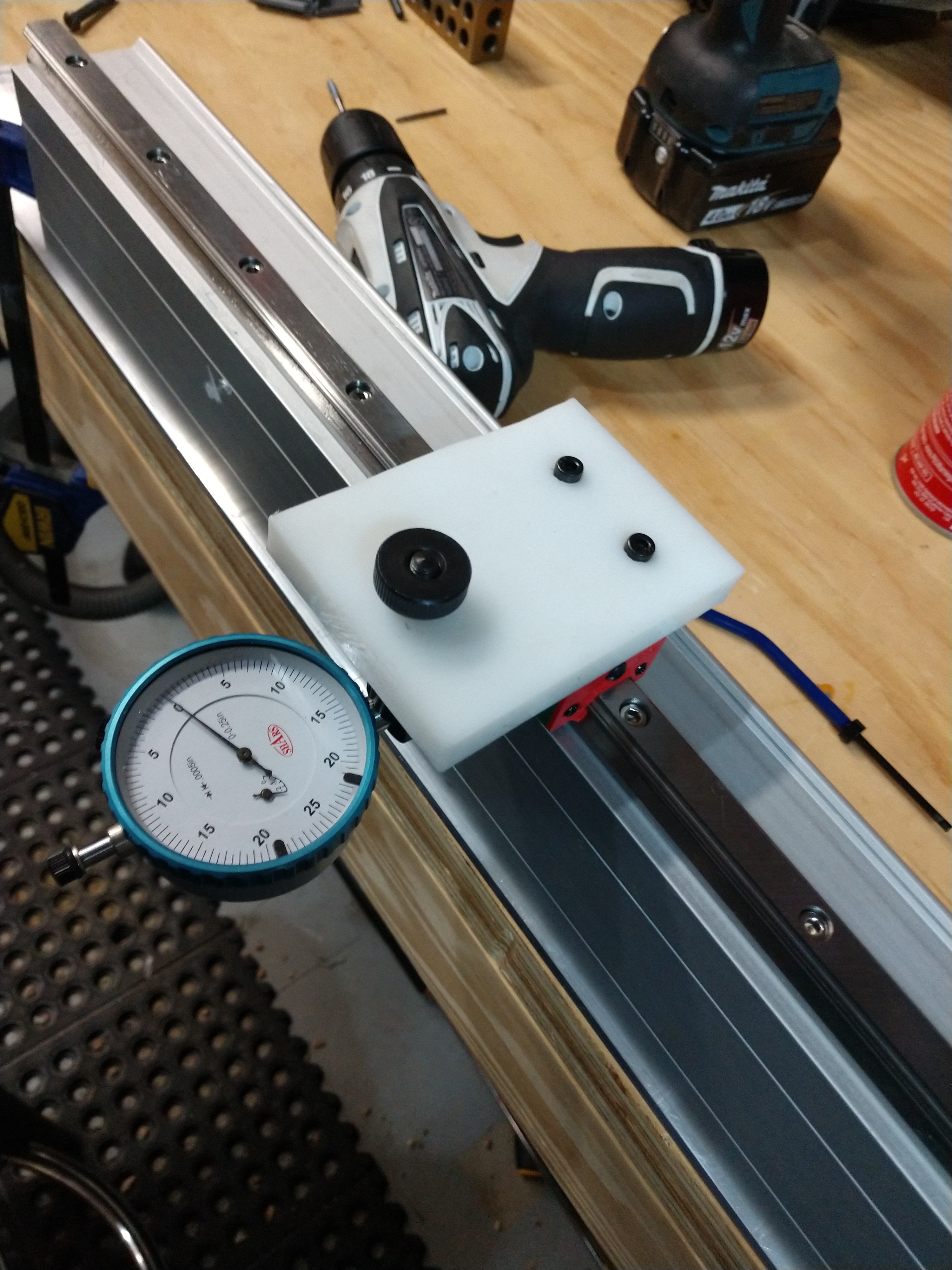
I 3D printed a few iterations to test measures, clearances, etc before manually milling the first prototype on a Little Machine Shop [Benchtop] Mini Mill. Which by the way, was the first time ever operating a mill, was very intimidating, even for how small it is.

I made several mistakes while milling out the first aluminum prototypes, broke a center drill, was in the wrong coordinate system on the DRO for a couple drilling ops, clogged and welded a 1/4" 3F, stalled the spindle with too large a bite (also caused the stock to shift… which I didn’t notice). Thankfully all that didn’t compromise the functionality … completely anyway :roll_eyes:

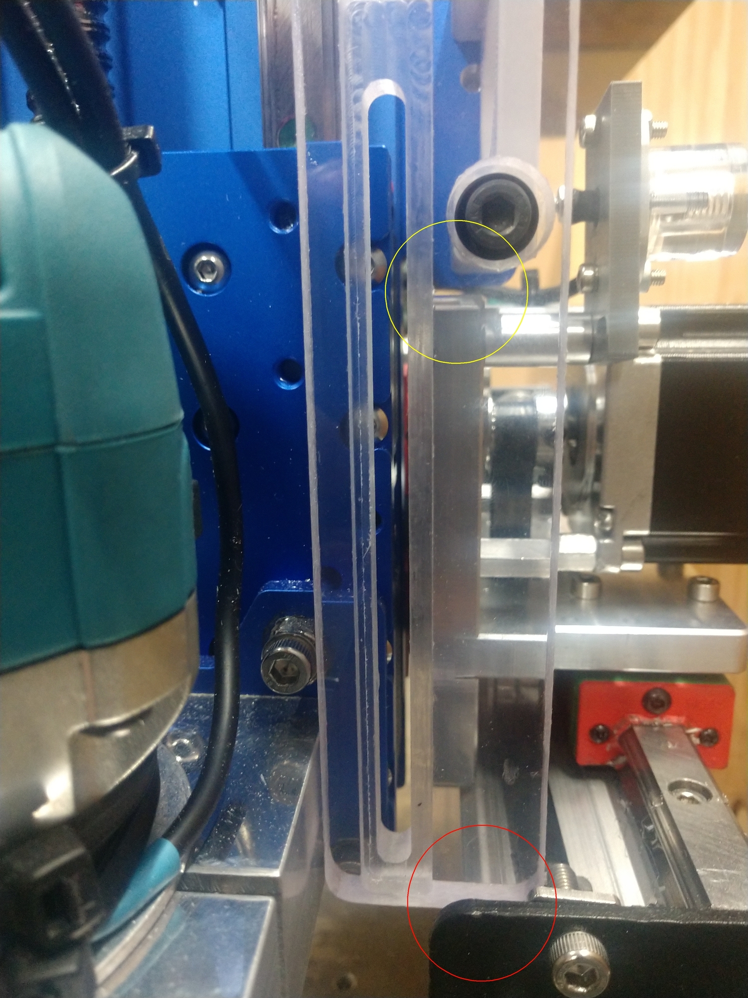
The installation of the prototype #1 went pretty well, but did have some alignment and clearance issues. For one, the belt idlers M8 screws interfered with the carriage blocks. So I had to grind down the M8 screw heads (because ultra-low profile M8 screws would have cost about $10 each x4)

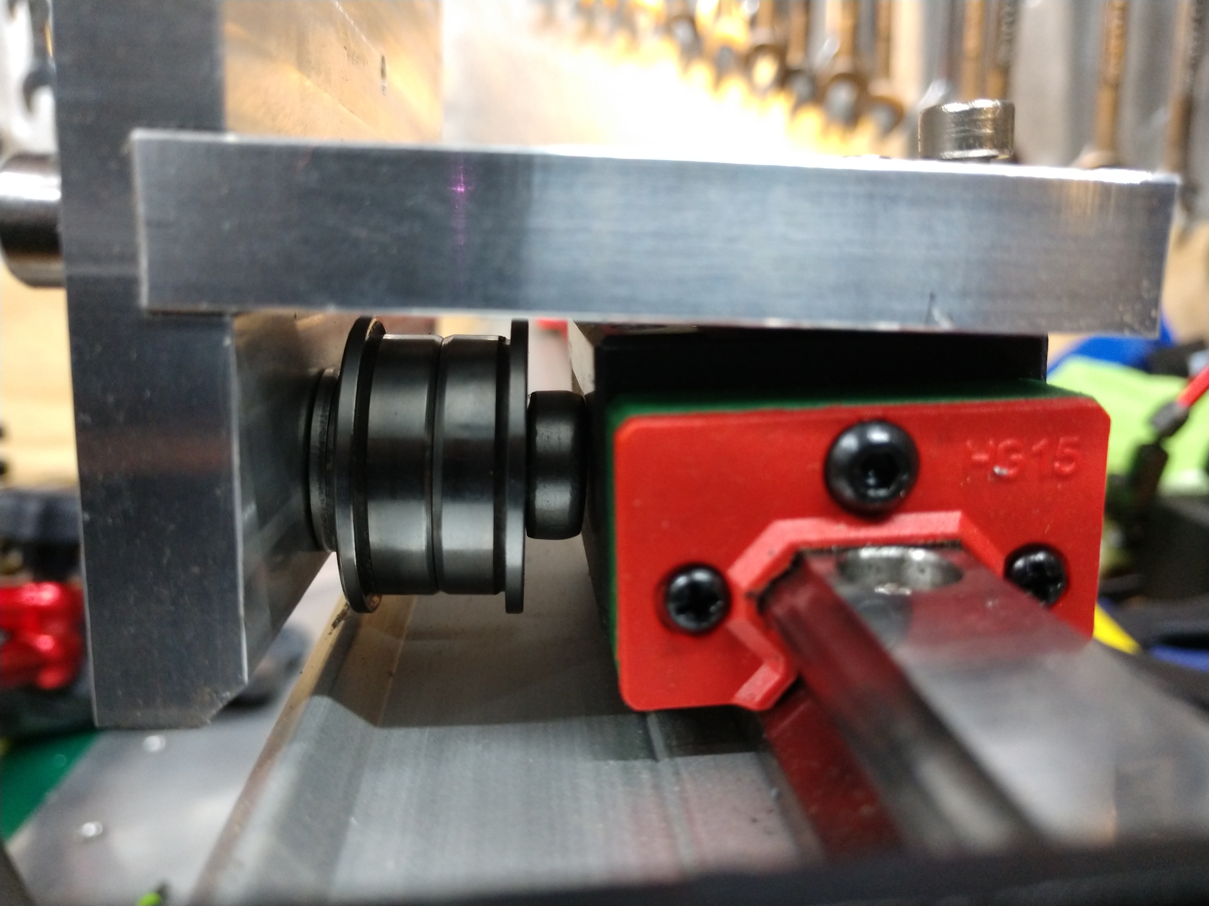
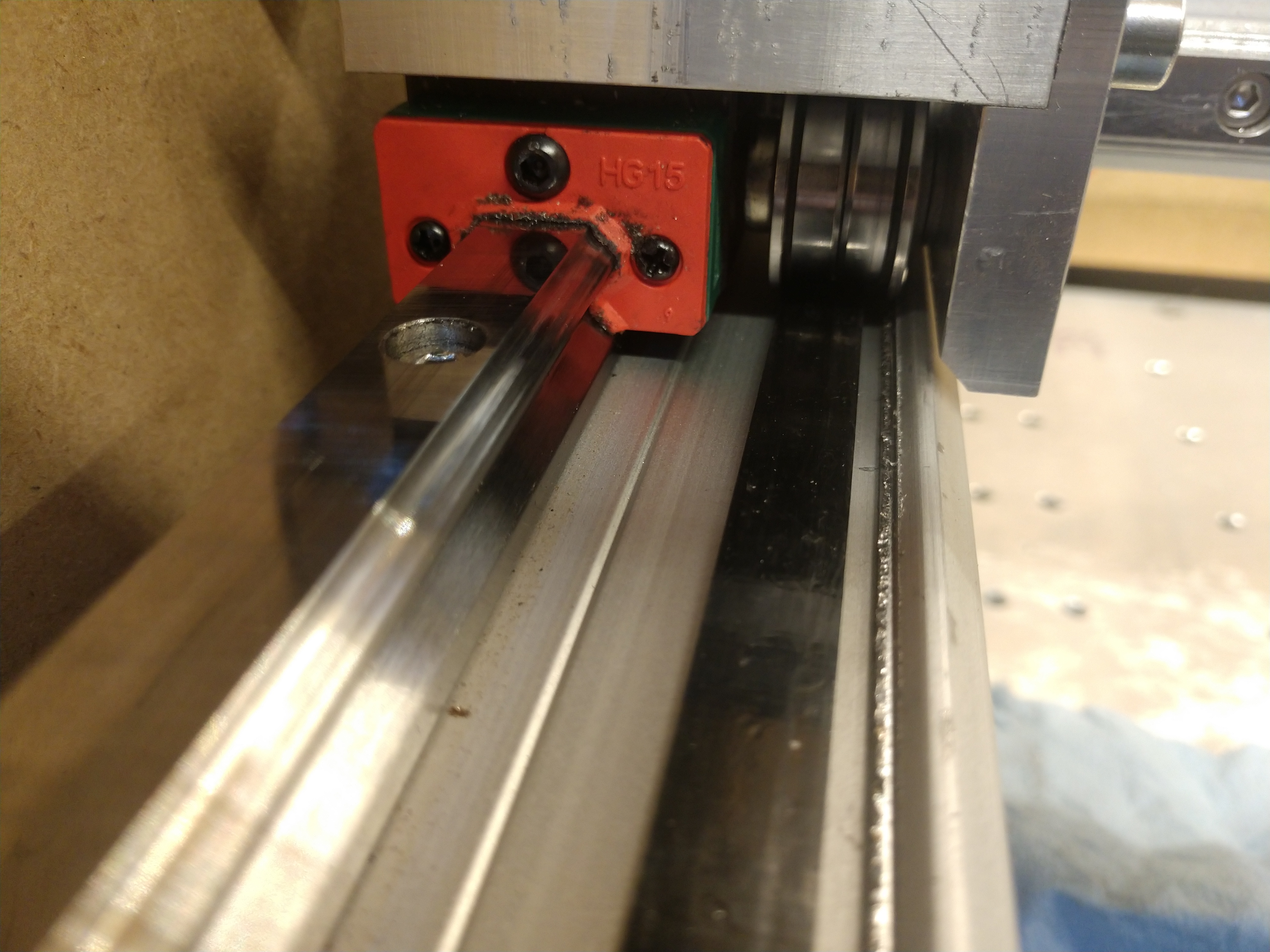
Second, the belt idlers themselves were not high enough and slowly ate into the SO3 extrusion. For some reason I didn’t think to put shims between the carriage and plates :man_facepalming:

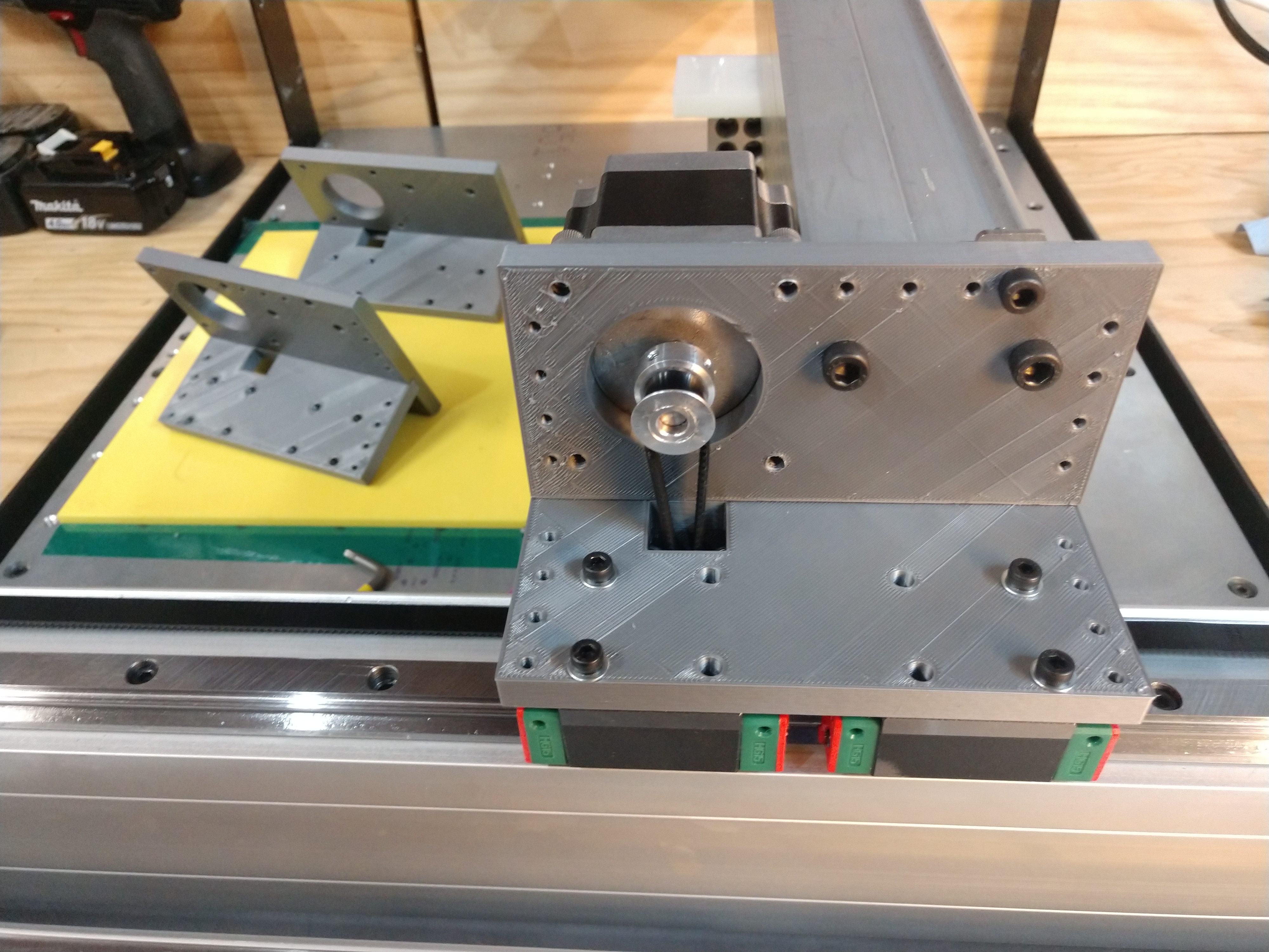
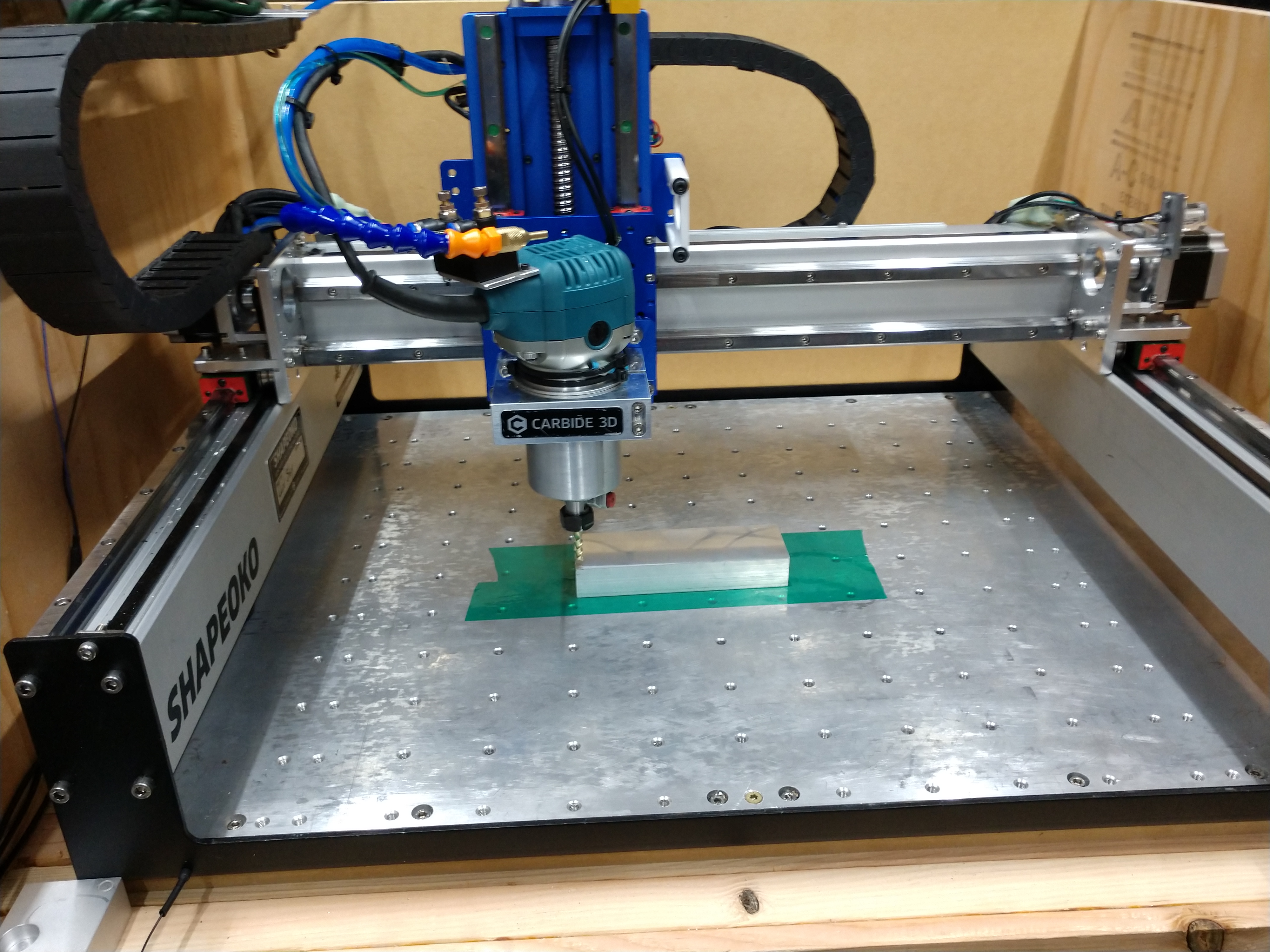
All these problems were on the Y-plate, which I had tackled first being the more complicated part. X-axis plate pretty much went without a hitch. I then fixed clearance issues and other odds 'n ends in my design. So I could make the second prototype of the Y-plates, with the SO3 using the first prototypes! This allowed me to add rounded corners and chamfering, as injuring my hands while handling the first ones was not uncommon.

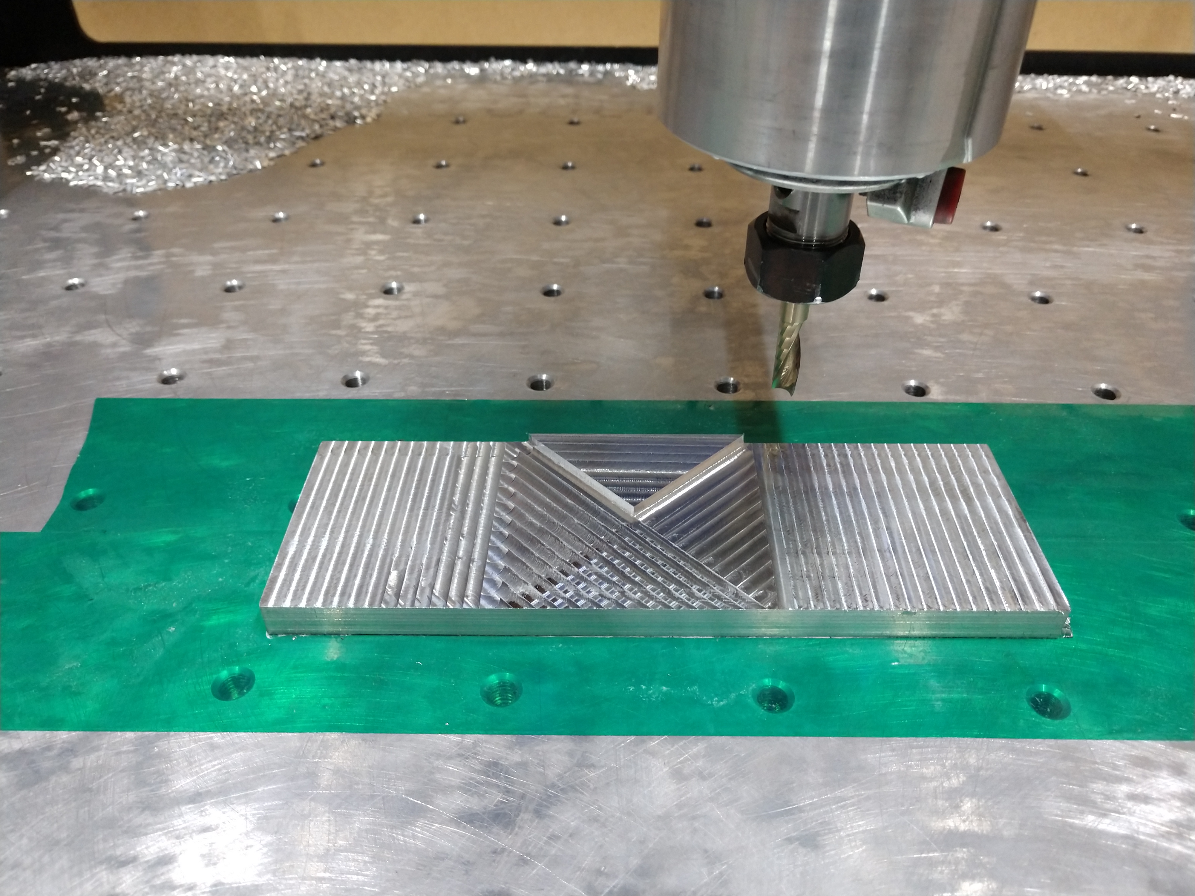
It was very awesome seeing the huge difference in performance cutting on the SO3 and the wall finish was amazing compared to the chatter mess before. Note: the face surface finish was done on the Mini Mill :stuck_out_tongue:

Prototype #2 plates turned out great and are now installed :slight_smile:


23 Likes

Oh you wanted to see it cut?

10 Likes

No no no no, NO ! Just when I thought I had my upgrade frenzy under control, and had managed to successfully ignore the other “check out my linear rails” posts, you come and post this and now I’m not sure how much longer I can resist the urge. Please please tell me you are NOT willing to share the design files, if you are I’m dead in the water :laughing:

Also:

this could be my signature.

6 Likes

You make it look so clean and simple!

Any reason you didn’t put the X rails as far apart as the extrusion would allow?

What thickness are your plates? They look around 1/2"?

This has been on my wish list for some time

2 Likes

Great work @DanStory😊.

I have received a set of HG15 rails for my machine also so thanks for the inspiration😊

1 Like

Seriously though, I would love to hear about your procedure to attach and align the rails to the extrusions.
I suck at anything requiring to do something by hand accurately, and I’m pretty sure that if I approached this naively, I would end up with rails that are almost ok, but not quite, and the movement would not be super smooth.
How did you reference the holes to mount the rails ? why kind of play is there ? How did you drill (and tap?) the extrusions with enough precision ? Do you then just assemble them loose, slide the gantry back and forth a few times, tightening screws as you go ?. I love reports on linear rails, but these kind of silly details is what I miss to decide whether I have a reasonable chance at doing it properly.

4 Likes

Great build! I don’t have the skills or tools to do such a thing, but if someone were to create a linear rail upgrade kit for the XXL, I would absolutely buy it…just putting that out there.

@Luke any chance C3D is considering a linear rail upgrade option? Need a moderately skilled non-engineer to test it? I’m always happy to help! :sweat_smile:

5 Likes

@DanStory what bit setter are you using? Got a link to it?

1 Like

Came out great @DanStory

This is basically the machine I wish C3D offered.
With the option between the two new Z offerings.

Note: Most likely at some point this year intend to purchase a stock size Shapeoko with the Z Plus.
Ideally not have to essentially replicate this effort with the linear rails and toss stock wheel parts to the bin. :slight_smile:

2 Likes

I agree entirely. These are the details that keep me from doing this too. Trying to align details over 500mm within 0.1mm tolerances seems super difficult to me.

2 Likes

Dan, I see that you placed the Y steppers on the outside, did you gain Y travel? A few months ago, I had suggested that as a way to modify the Shapeoko to inrease Y travel by a few inches.

1 Like

I plan on providing the designs (Sorry :)), but I hope people understand, I was gonna charge a few bucks for it, as lot of time and money went into it. Changed my mind.
Also… is it weird that I used inch measurements with metric hardware? :laughing:

They started at 1/2" and I surfaced them down to 3/8" with a flycutter on the mini mill to help with flatness/parallelism. I was gonna try 3/8" ATP-5 later, to reduce operations and setups but we’ll see (as <=0.5" is spec’d at 0.005" flatness).
2-sided ground flat 6061 is a little too pricey.

This would be one of the design mistakes I made for the X-plate, after I had the Y rails and plates I kind of rushed on the X, I was too excited. I have widen it in my design since then, but have yet to take a big sigh and remount the rail with a wider stance. At that point I might do an epoxy fill, I did skip that I filled the extrusions with sand+pea gravel mix, this increased the weight of each by ~10 lbs.


It is not for the faint of heart, that’s for sure. Y rails I mounted both to spec of my drawing, I scribe’d a line for the rail center using layout dye. Then clamping the rail on, aligned the two ends from extrusion face to rail edge using a digital caliper, referencing my drawing measurements. I center punched the two edge mounts, using the scribe’d line as validating center alignment (I didn’t capture this with a photo). I drilled and tapped those two holes, and used them as a mount for the rail again to center pouch the rest. Firstly I should have used a transfer punch (didn’t have one at the time), second I’m a gorilla with M4 tapping I have found. I didn’t do proper chip clearing and chowder’d several threads or cut very weak threads. Thank god for E-Z Lok thread inserts.

I ended up purchasing transfer punches and a M4 thread form tap afterwards for the X rails, that worked so much better (G-Wizard has a nice reference on drill sizes for both cut taps and form taps). Also got spiral flute taps up to M8 for the other tapping I had to do on the plates themselves, highly recommend vs hand taps. Basically, the lesson here is to have the proper tools up front (and don’t be a gorilla) :slight_smile:

When it came to alignment, most of it wasn’t difficult. I first aligned the rails to the extrusions, checking parallelism to the side. I also double checked height deviation, which was <0.0005", both on the face of the extrusion and from bottom to carriage block using a cheap little grade B granite surface.

Aligning the two Y rails to be parallel was a little harder, but mostly cause of the span. The most PTA part is the height parallelism of the two extrusions AND the bed. Because there is sag in the bed (which I tried to mitigate) and it being the typical 6061 plate, it isn’t very flat itself. I basically used a surface height gauge, going back and forth on the front two corners then the back two, using a dead blow and machinist jack for many hours to get them as close as possible. Eventually I will replace the bed with a thicker ATP-5 plate for better flatness.

Yeah, I was gonna get the BeaverCNC HD Kit eventually, instead of going this route but that is no longer offered :frowning:

That is the TSM from Vers.by, I actually need to hook it back up.

I designed the plates to support both, mount as stock (steppers in the back) or flipped like I did. Honestly, there is no reason to have them in stock mounting position, as the X-rails push the Z further forward. So you regain some of the Y workspace you lost. I basically made their length as skinny as possible, I also incorporated to be as short as possible, to clear the HDZ mounting ears. Just have to watch out with the front frame now :laughing:

7 Likes

Yeah, with the mounting slop, inaccuracy in steel frame, extrusion cuts, bed sag and having the required tools, it isn’t a simple task. I actually had binding issues with my X axis and not Y, but that is more due to one bad carriage block. The mounting face was not ground to spec which required shimming between it and the plate, and it did not roll smoothly. I rebuilt and cleaned it, but still not great. I will just have to bite the bullet and replace it.

6 Likes

After much internal debate, evaluating options, store platforms, my life ( :wink: ), I decided to open the designs to the public freely. Don’t hate me Julien :stuck_out_tongue:

Feel this will give me less burden, with my perfectionism nature and limited time as is. I don’t think I’ll ever get them to the point where they are “flawless” and I got other projects I want to do :smiley:

Note, I have only uploaded the Y-Axis model, as that I feel is in a finalized state. I plan on making and testing my design changes for the X-Axis next week and have those uploaded too.

18 Likes

Oh my. How do I unsee this thread. There goes my plan to reduce the length of my Todo list :slight_smile:
But, :+1:

5 Likes

nice @DanStory !

should toss them up on GrabCAD as well.

3 Likes

Good idea! Was thinking CutRocket too, though wouldn’t have the CAM ops, at least for the time being (they are still very in flux and might be aggressive for stock SO3 :laughing:).

1 Like

Merlin’s beard!! I have seen things you people would not believe, attacked ships in fire off the shoulder of Orion, I have seen sea beams glitter in the darkness off ten housergates all these moments will be lost in time after seeing so3 on hiwin rails (little nod to blade runner) nice BA nice!

5 Likes

This topic was automatically closed 30 days after the last reply. New replies are no longer allowed.