Since I have owned the machine, I have had issues with the control board, namely the YL connection, in fact when I went to remove the lead today, and the entire terminal base came with it… this was while i was on A VIDEO CALL with customer support - shout out to Fleming who was awesome.
I was on the phone because last week when my computer went to sleep during an operation, technically my fault, but you would think there would be an override of some sort, so as the machine lost contact, it moved into a material support which knocked off the lower clear dust shroud into the spinning bit, which cause havoc and then some. Broke part of the actual spindle, and the clear bottom dust boot is destroyed, along with the part. I know the gantry was pushed back while i was trying to minimize damage. I reached out to CS and this is where fleming came in.
I replaced the router with a nib Makita, sorted out the SO, reinitialized it and proceeded to cut another piece a material, and this time the cut/tool paths were all skewed, same exact working program, but the parts were all out of dimensions badly.
I spoke with Fleming and we troubleshooted the y axis lead by unplugging it, that’s when the terminal and wire terminal came completely off. I also noticed one of the pins in the wire terminal, white, was not clicked into place, and this was the same issue I had when i first bought the machine new last year. So I made sure all of the connections were solid, the lead was working, pushed the terminal and plug back in. Now that the connection was tighter(?) I decided to run the same exact program again, and this time it did not crash but the dimensions of all the parts were skewed again, completely unusable.
The plot thickens and here is another clue… I noticed that the position of the bit in conjunction with the bit setter was no longer in the center of the button! I know this because on a previous call months ago, one of the reps helped me center it by changing the parameters in the settings. But now it isnt!! (Insert dramatic music)
My thoughts are that even though the control board seems to have the plug inserted and pushed firmly against the rear board, somehow the connections inside are dodgy and causing small shorts? Or did the entire machine get bent because the bit setter is no longer aligned… or both? Of course it’s both, why wouldnt it be… sigh.
Anyone have a starting point? Take the rubber drive bands off and re-center the machine?? Somehow check for squareness in the gantrys?
Light it on fire and drive over it with an excavator as my friend Whistlin Diesel suggested? Hopefully not.
This has absolutely put orders and my business at a standstill… I use this to make parts so any help is appreciated.
You can check square without disassembling anything.
When I setup, I measured from Rear of YL to Front of YR, Next reverse that from Rear of YR to Front of YL.
Slowly move the “X” rail, check your measurements as it is progressing. See if the measurement changed while moving “X”.
I used a square I knew was true to check the “Z” plate and router as well as the “X” rail to the waste board and both “Y” rails.
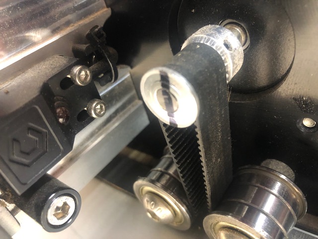
This should give you an idea if it is out of square. Check the pulleys on the stepper motors in case the jolt was enough to cause issues. I put a witness mark on mine.
I have a new Windows 11 laptop. I always turn off the screen saver and the sleep and they are set to “Never”. This is for a couple of reasons.
When running a Shapeoko job I dont want my computer to go to screen lock and/or sleep.
At night I listen to a “Gentle Rain” youtube video to go to sheep. Again I dont want my machine to go to sleep and quit running.
I started out with the original monitors that would actually burn an image into the screen if you left it running the same thing day in and day out. I used to see terminals in data centers that had the screened burned with the image of the terminal on it even when off.
Modern screens cannot burn an image into the screen. That is not say that leaving a screen running 24-7 does not cause problems. Certain screen conditions max out the screens current and that can have long term issues with the screen/monitor going dead. But they will not burn an image into the screen.
Even if I leave the room I dont want my computer to go to sleep or lock my screen. I have a secure environment where I dont have to worry about unauthorized use of my computer. Now if you have kids that like to get on your computer that is a different matter. The things I see on the internet as an adult are shocking but for an innocent kid that could be bad.
I once was helping my grandson with a school project. We were searching for pictures of castles and one of the first things to pop up in the google search was a S&M site that had castle in its name. Even the screen icon was offensive to look at with an 11 year old kid. So lock your screen automatically if absolutely necessary but going to sleep is another thing for me.
Squareness tends to be good by default on a Pro, I doubt this is it but it is worth checking that when you (slowly) move the X/Z gantry all the way to the front (or back), the left and right sides contact at about the same time
The second factor is belt tightness: not so much how tight they are (well there is a minimum tightness to have) but the fact that they are similarly tight on the left and right sides.
If the router position above the bitSetter position is off in the Y direction only, it might be that belts got loose over time.
Can you upload pictures of the skewed parts ? it may give us a hint as to what is going on.
i will def upload pics in the morning, the machine is out in my shop.
Yes, in fact the bit setter position only shifted on the y axis toward the rear of the machine. This was not an issue previously, but after the crash it is. All parts on the y axis towards the rear of the machine are off skewed moreso than x.
Thank you, my computer is a fusion 5 tablet on an attached stand running windows 10. It is dedicated and runs only carbide motion and email, to accept files. Once the job is over i now just turn it off. The extra step isnt a big deal.
SHHHHHHWOOOOOSHHHH that was the sound of your response going over my head. Im more visual and have to see things, versus reading. But good call on marking the drive gear, do you mark both side and then see if there are any discrepancies? Not i am visualizing this correctly.
On the Picture of the pulley you notice the line I drew goes through the pulley and the shaft it is mounted on. I have done this on all pulleys on my machine. So if I get an issue that needs to be figured out, I can glance at the pulley to see if it has spun on the shaft.
I will dig up the installation manual and reference the pages regarding checking for square.
Another thing to check is to pull the “X” gantry forward (slowly)while the machine is off. When you get to the end of it’s movement, are both sides touching the end plates equally?
XXL PRO, thank you. Although I did slide the x gantry to the front and both sides touched at the same time, so that would make sense only if its square. It must be the dodgy connection inside the control board, oh, they’ve been so kind as to send me a replacement board and the YL extension wire.
Standing by for it, once it gets here update the post. Thank you to everyone who took the time to help, it is highly appreciated. Stay tuned…
New control board, check
New wire lead, check
Was the y axis motor not locked, check.
Did the y axis motor magically connect and start working once the CB3D rep called me, check.
We ran it through some paces, and everything seems good. Prior to the call from support, with the router on, the left side had about 3/16 play, back and forth, whereas the right had none. Now, both sides have very little play, normal if you will. So, after a thorough once over, I am going to run a file today and hope for the best. You guys rock for your advice, thank you.
Well, I wish I had some good news… After all of that I loaded up a new piece of test material, and ran a file. The first tool pass is a 1/8" carbide composite bit, doing 30 through holes, and 20 of those have a counterbore inside them… After about 8-10 holes i could see the circles were skewed and oblong drastically.
Before running this pass I adjusted and tightened the belts, which were not loose: but i went through the process nonetheless.
I have double checked every screw structurally and everything is secure, outside of the play in the YL motor, which I think is the suspect. Waiting for support to contact me. Definitely a learning experience relying on one piece of machinery for my business, never saw that coming. Hopefully it gets resolved soon.