Just purchased a used Shapeoko XXL machine. Tried to create my first basic project for a 3 inch x 3 inch x .75 in board. I zero in the X, Y, Z to the center of the board. When I go to start the project, it says I need to change tool bit. The tool bits I received do not have any numbers on them. So I have played around trying to change the file to match the tool in the drill with no luck. However, when I click resume to bypass this, the z position pulls away from the board and then starts running.
How can I keep the z position as-is and use the tool in the bit to run the job without moving?
Thanks.
I use the center for most of my projects. During my centering I usually use a vee bit to find the exact center where I have an X. I draw a line from the corner of each corner of the board and find the center and use that with the vee bit to center the bit. If you use a round bit the center is harder to find because of trying to view the bit from all sides to find the center. Once you set X and Y zero it is persistent until you change it even over power cycles. So if you set X and Y zero it is set and you dont have to change it even if you change the bit. However you need to be precise in setting X and Y zero or you project will be slightly off center.
So you need to figure out what bits you have. If they are C3D bits you can go to their home page and the shop button and compare the bits you have with what they are selling. The #201 is a 3 flute 1/4" bit that comes with most machines. So measure each bit with a caliper and count the number of flutes and compare and contrast with what C3D has. If they are 3rd party bits you do the same thing and I use the closest equivalent bit from C3D. For instance the #205 is a 2 flute 1/4" down cut bit. So if you have a 2 flute 1/4" bit that is down cut then just use the #205 in your design. You can make custom tools if you can find the OEM manufacturer of your bits and go to their sites and get the specs of the bits. I would not recommend using the OEM F&S because they are usually for industrial CNC machines. The C3D recommended F&S are conservative and you can increase the feed rates in CM by simply clicking on the software button to increase up to 100%.
If you have a BitSetter then the Z zero is consistent no matter what tool you insert. The caveat is you have to change bits only when requested to by the software. If you manually change bits without going through the software interface then you lose the calibration between the BitZero and the internal coordinates established during homing. If you do not have a BitSetter then you need to run each tool path separate and set the Z zero with each new bit with the paper method.
Perhaps your file calls for the Z axis to be set at the spoilboard. If that is the case, you will cut air when you physically set the Z to your wood surface. Check your design file to see if the z setting to to be at the spoilboard or the substrate surface.
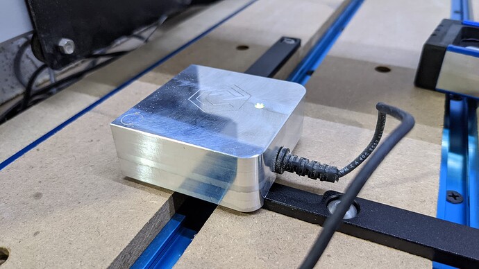
I finally got it to work. I had to play around with the thickness value and retract height on the job set up window in carbide create. I thought the thickness was based on the width of the board. I do not have the bit setter, I have this other silver thing that came with it (forget the name) to help set the bit. Not sure how it works though. Still playing, but at least I got something to cut. Thanks for your help.
That silver thing is the Bitzero which is used to um, set the zeros.
If you don’t have the bitsetter then make sure you don’t have it enabled in Carbide Motion. That means your tool paths should be single tool only and you have to rezero after every bit change either manually or with the Bitzero.
Without the BitZero create all your tool paths. Order them so the least intrusive is cut first and cut out usually last. Then save your file. Go back and disable all but the first tool path. Save the file with a new name and then run that new file. Then open the second file and disable the first tool path and enable the second tool path and then save with a 3rd name. Run that file and then repeat until all tool paths are run.
The reason to save the original file with all tool paths is in case you have a mess up you still have the original file to create the individual tool paths into a separate file. We are all prone to making mistakes.
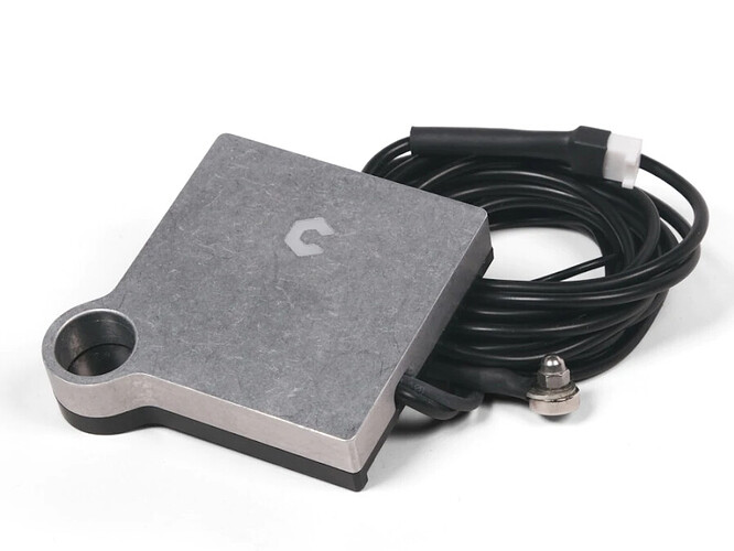
The Bit Zero has two versions.
V1
V2
In Carbide Motion you must tell it which version you have. After that it is persistent. The V1 you can zero on the lower left corner and set X Y and then the Z on top of the bitzero. There is a lip that is on 2 of the 4 sides of the bitzero. On a lower left corner you over hang that lip off the side of the material. You can also just zero on top of the material by placing the whole bitzero on top of the material and not over hang the lip. When doing an X Y and Z you must specify which Bit you are using and internally an offset is created to set zeros based on the size of the bit you chose. The V2 is slightly different and you can still use a bit but it originally came with a 1/4" steel pin you insert into the router. The steel pin is the prefered method to set zeros.
The BitSetter is a handy tool to have. However you cannot do Advanced Vcarve without a BitSetter. But the user fenrus had an application that would take the advanced vcarve file and create two separate tool paths so you can still do advanced vcarve without a BitSetter. You will have to search the forum for the link to his application.
To use the probe function for the BitZero you must be within 12MM of the BitZero circle for V1 or the hole in V2 for it to work without timing out. There is a magnet attached with the BitZero and be sure to secure it so it is not randomly grounded to something when not in use because that can cause problems.
This topic was automatically closed after 30 days. New replies are no longer allowed.

