I got started on Fusion last week, played with it for quite a few days and it has a lot of cool features! As usual I spend more time trying to get vertices to snap to grid then anything else…
For me the best way to learn a new editor it is to get lost in a project.
I started with the concept of building something simple for my second piece that I could cut out with the limited tools I have available.
I like the concept of cutting out a jig with the same body as the item to flip it over and carve out the other side. I have experimented with it and I think I have it figured out mostly…
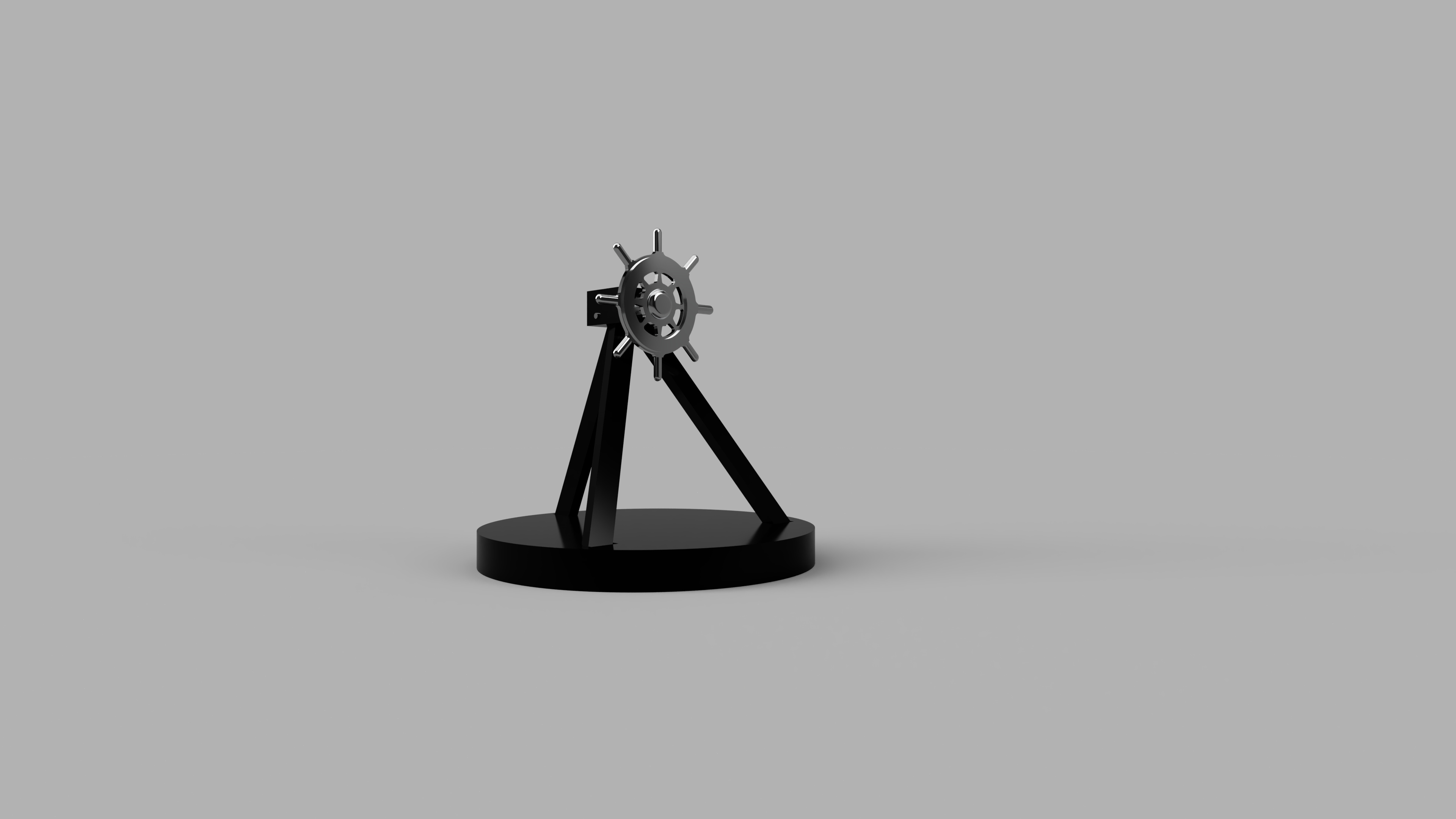
So what started out as a simple ships wheel learning how to use fusion grew into something else and just ate up four days of my life!
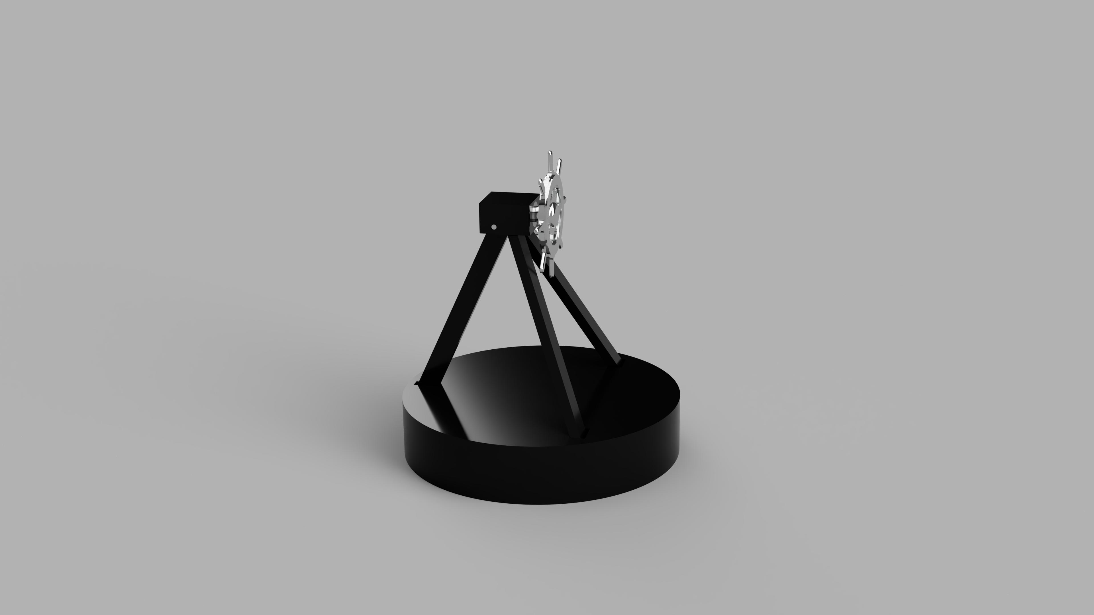
I still have some design and cutout work to do but I think it is mostly figured out. The worst was the top piece on the tripod it needs 2 jigs and 3 jig operations.
I guess the best way to combat sharp corners and round bits in a 2d environment is to chamfer every socket inside corner? Not something you deal with in a video game editor lol.
Ingredients are:
32x9.25 x .75 red oak
1/4 x 5/8 sealed bearing
Aluminum 1/4 spacer
.125 pin
1/4x20x 3/4 Allen head socket cap screw
1/4x20 thread tap
4.20x4.20x3/8 6061 aluminum rectangular bar
Black primer and paint or stain
So far I am working with these tools:
1/4 flat, 1/8 flat, 2mm flat, 1.2 mm flat
I have practiced cutting out the wheel with wood and am working on getting the proper tools for aluminum. Would like to make the whole set in both wood and metal.
Will post more pics of actual pieces when I get them cut out.
Having a blast with my Shapeoko, thanks Carbide 3d!
Thanks it went from simple little piece to never ending chore to finish haha… Just got done designing it in fusion, am currently working on tool paths which will prob take 20 hours to process lol… I tried aluminum foil. I ordered shim stock from amazon prime. Might switch back to the silver one with the eccentric bolts.
Had some big design flaws and a bunch of screw ups but I learned a lot about what to do and not to do.
1 mm bits seem too small, I will re-design depth and inside corners for 2mm and up to 1/2 deep, or 1/8 and up for deeper.
I built my spoil board and work piece too large I needed to account for Suckit ears.
Using a special hs 1/4 router drilling bit was fine in MDF but it burned the Red Oak and might have destroyed the bit. Will use end mills for drilling holes in hard wood.
My friction jigs worked well but I did not realize it was not centered exactly and I destroyed the piece by putting it in bottom up instead of top up. I will change my cutout and jig system to not use frames in the future. 4 small tabs will not do it. Will also design thicker parts less prone to chipping.
Switching from locating pins to magnets since they were not needed anyway due to center box locating the lid, also magnets will keep the lid closed.
Putting a chamfer on every surface except the inside floor edges. Have little wooden razor sharp edges everywhere!
The Red Oak I had laying around for 10 years was warped worse then I thought. I went out and bought some 11.25 wide planks that are mostly straight for the next try.
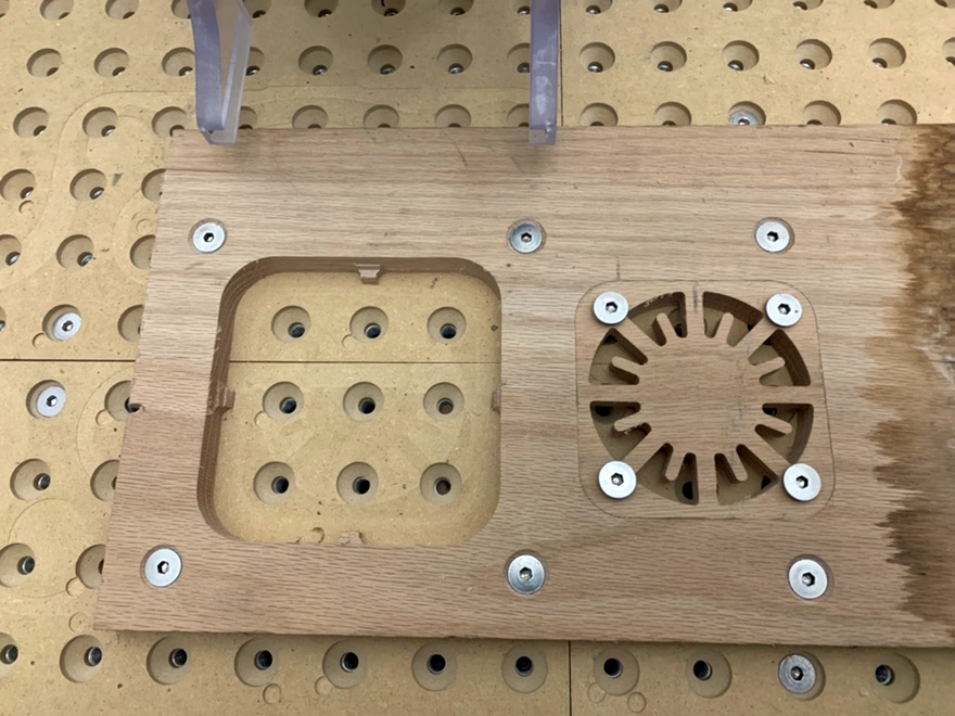
I designed a 4 piece MDF XXL board for the 1.5 inch bolt pattern aluminum base with out of cut range ledges to have a level workspace for the next production. The picture is top left. I had to lie to the editor to get the 82 degree V cutter to do my countersunk holes right. What a dirtbag!
V2.0 coming soon!
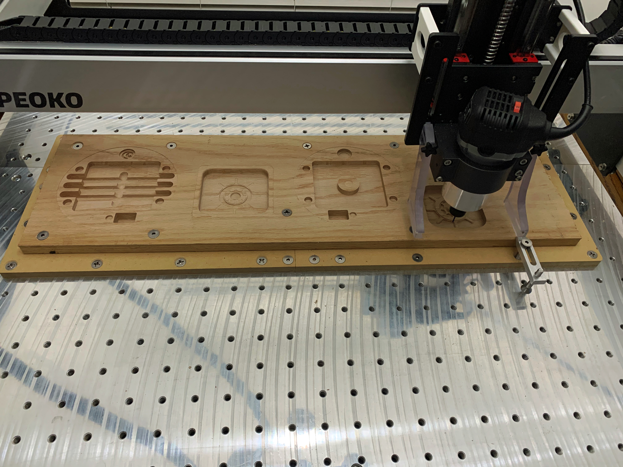
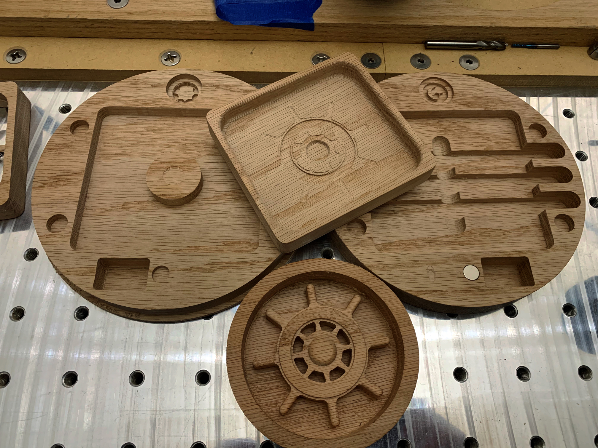
20 hours later… V2.0! lol… (Crickets) Smaller and better! Fits on a 11.25 x 24 piece of Red Oak, which Lowes stocks, if you can find one that is not bent like a pretzel.
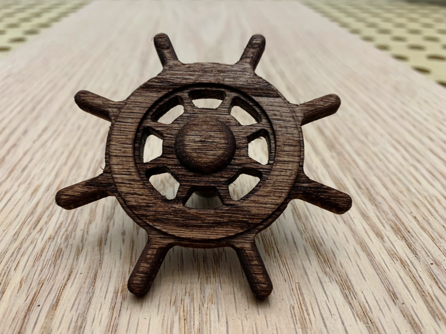
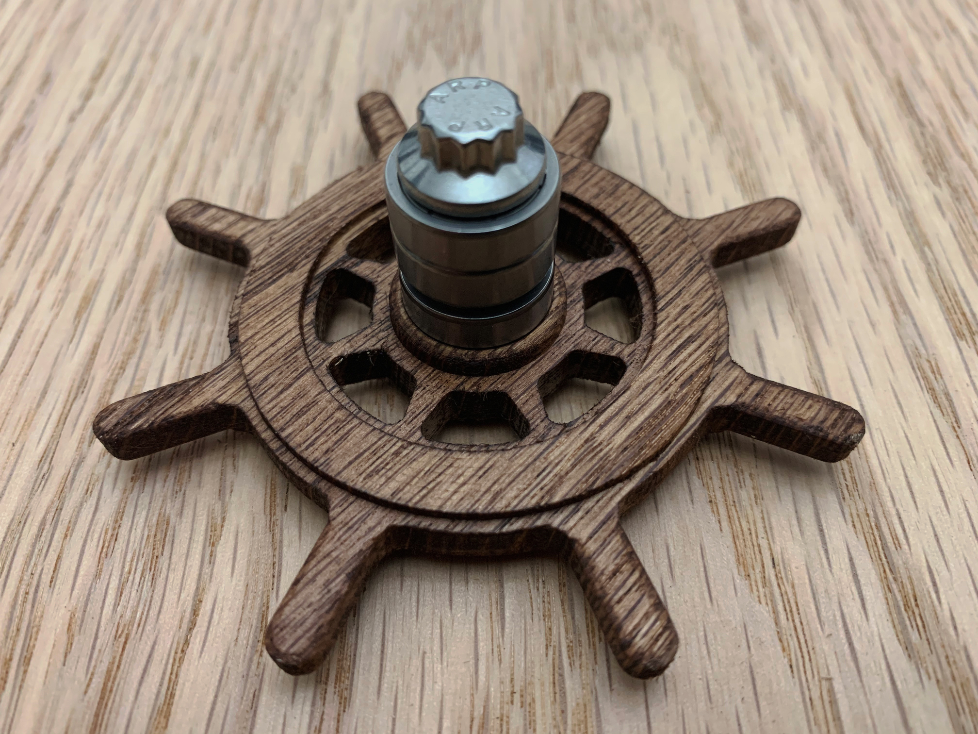
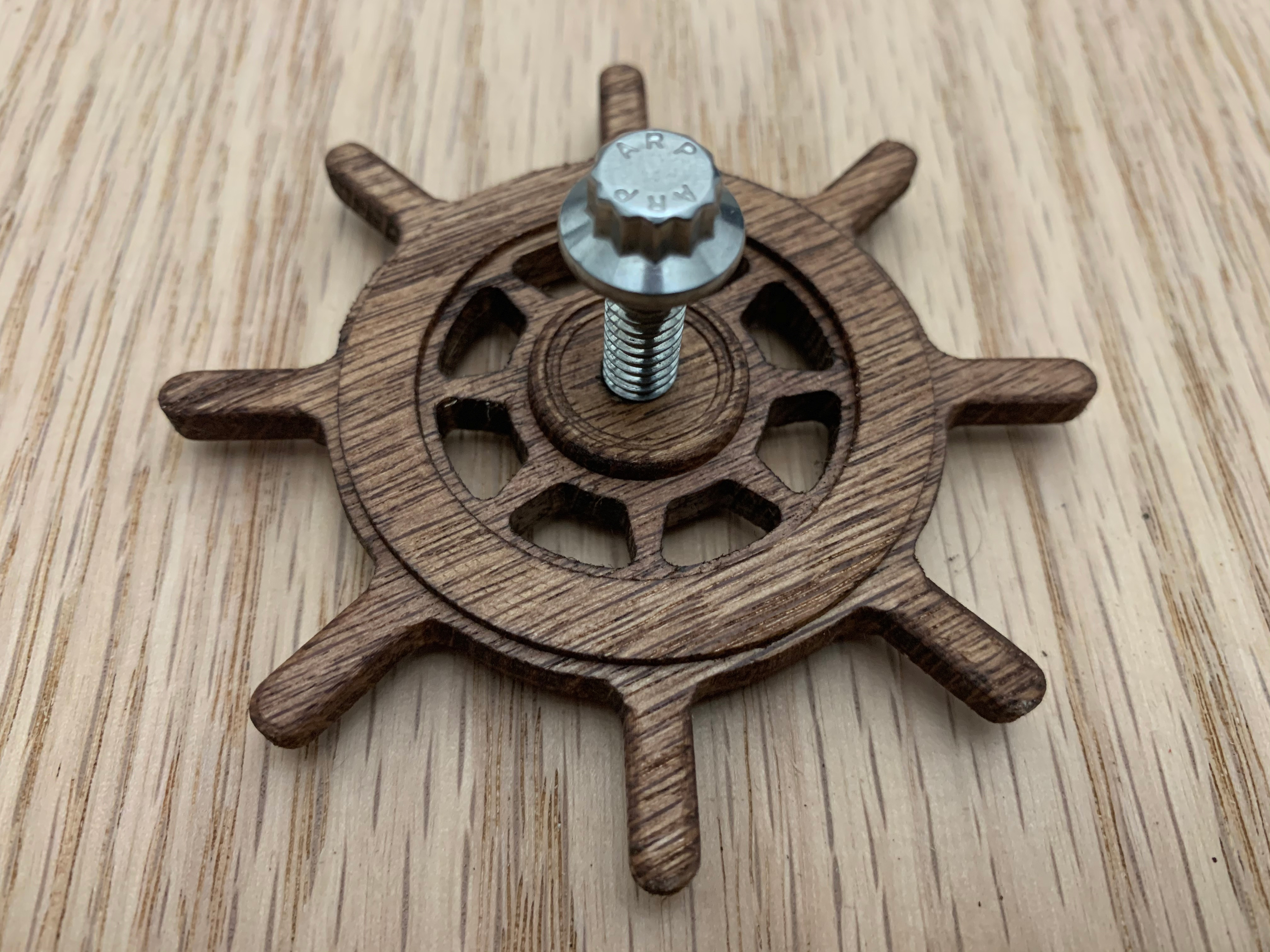
Finally after many failures got a reliable process figured out for making these 3" ships wheels.
The Bearing race works perfect and it spins very nicely on a 1/4" shaft. Picked up a lot of awesome techniques from my fails. Check out the fit on the jig. It was not coming back out lol. Friction welded.
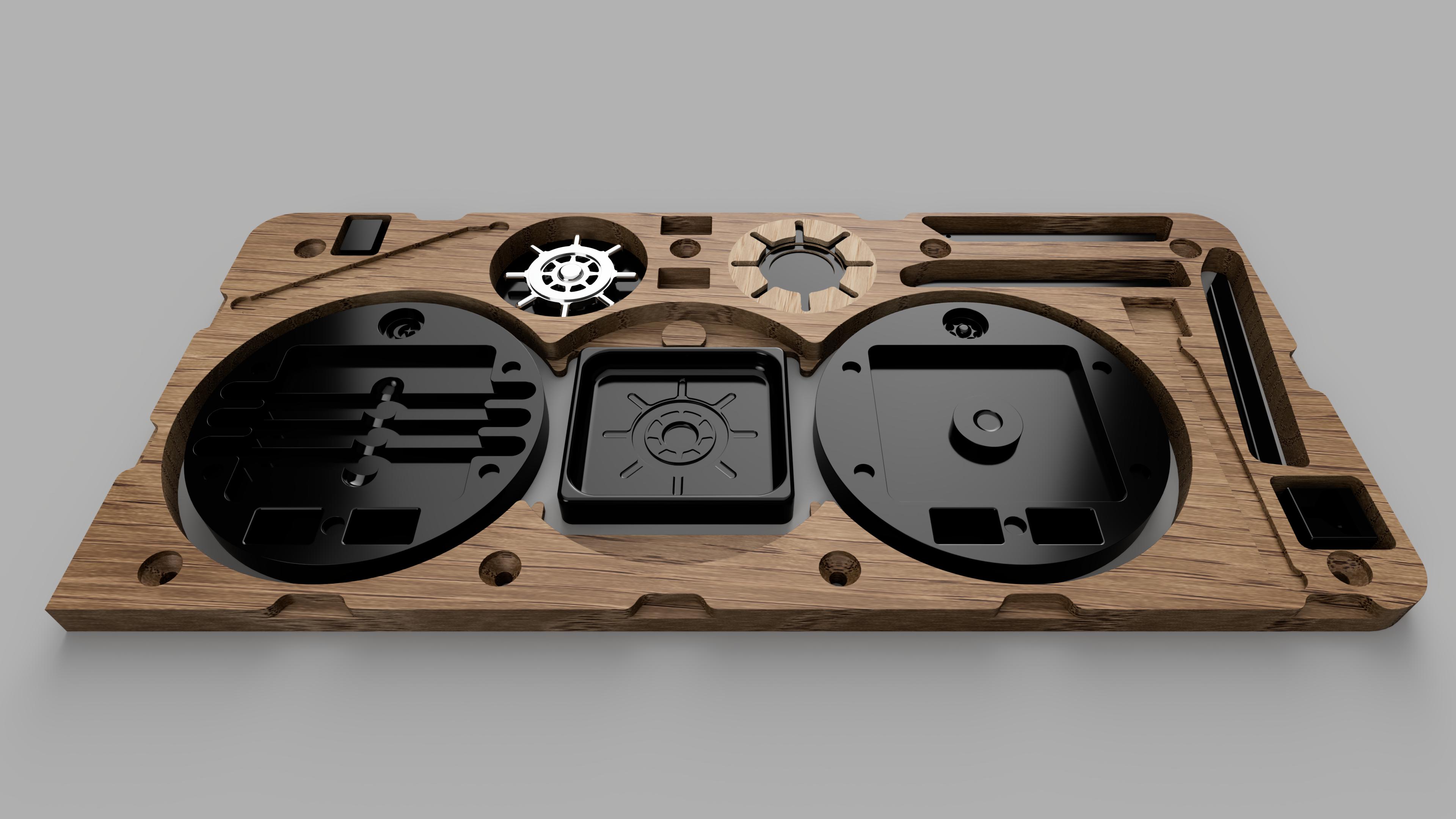
V3.0
New wheel jig method
Tool box to hold bearing, spacer and bolt with hold down on lid.
Cut out for Allen wrench
Used available space from new jig method to add clamps for tripod leg jigs.
Switched to tabs, way better for me then onion skins and are removed effortlessly with my table router.
Hah this is one of the first pieces I designed after getting my hands on Fusion 360 and a Shapeoko.
Wondering about my thought process and why I bothered making those outside recessed clamp slots. Need the countersunk bolts to hold down the work piece to make them lol? 3 round edges and one sharp for the touch probe. Don’t want to get hurt on those virtual sharp edges!
I made an few attempts to document my projects on the forum as I was teaching myself, but I was only getting a few likes and no comments and ended up feeling stupid and stopped. I was telling myself at the time, at least I can come back and see how I got started or something along those lines.
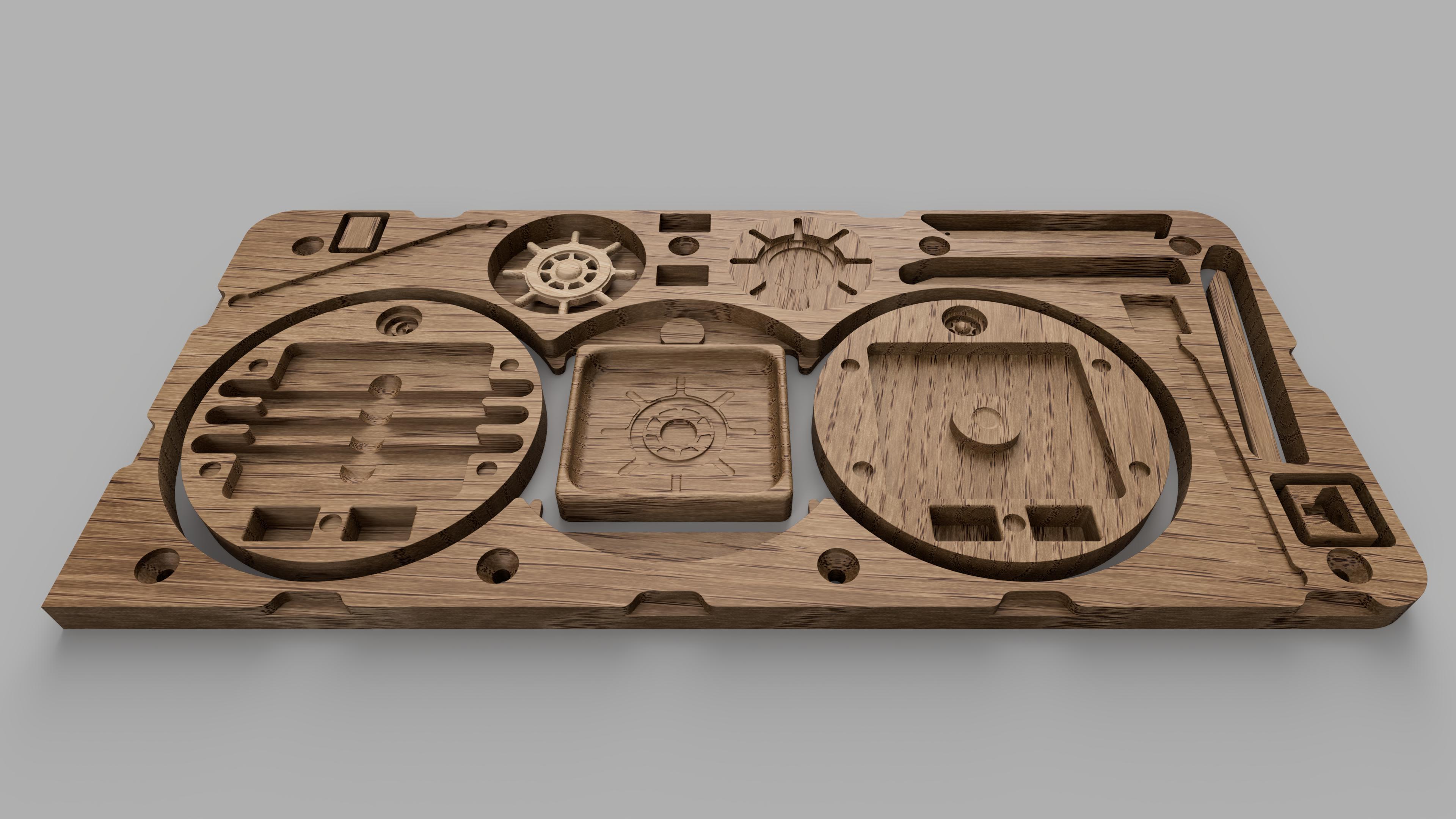
I generally rely on 3D toolpaths. They need at least a 1/2" of clearance around the part you are carving when using a 1/4 end mill so the tool has enough room to properly use slot clearing etc. I design to use a table router to easily remove tabs. If at all possible I try to hide any area that had tabs and try to cover them to hide tool marks. I always do any interior carving first and cut out the tabs last so it has a stable base.
I also leave a small gap above the tabs before using any bevels or angles, so the router has a smooth surface to roll on.
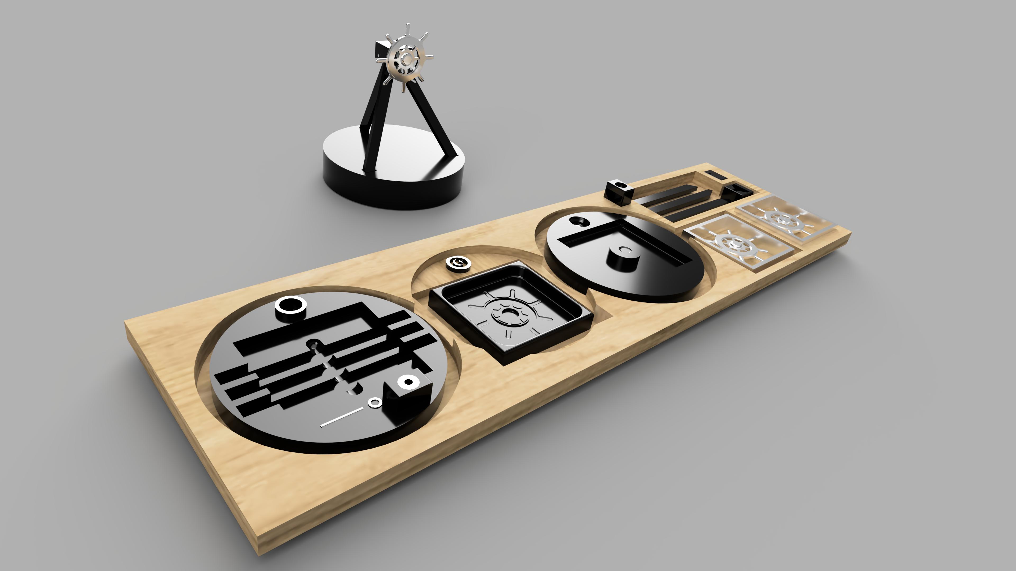
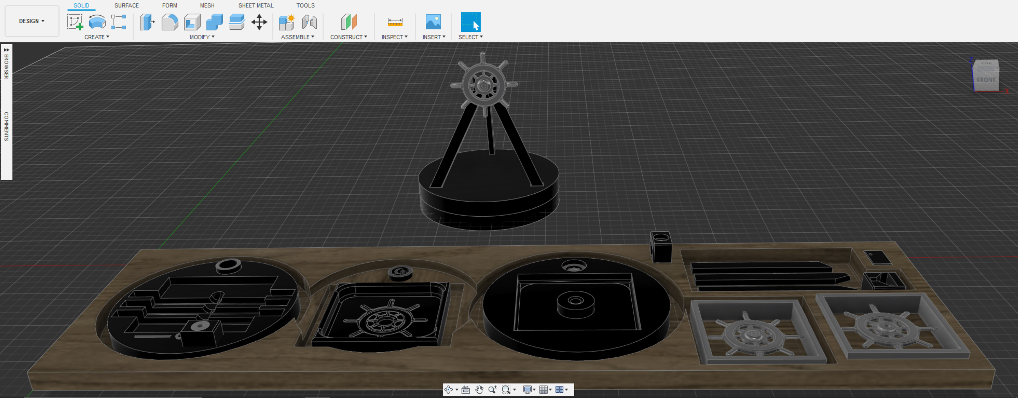
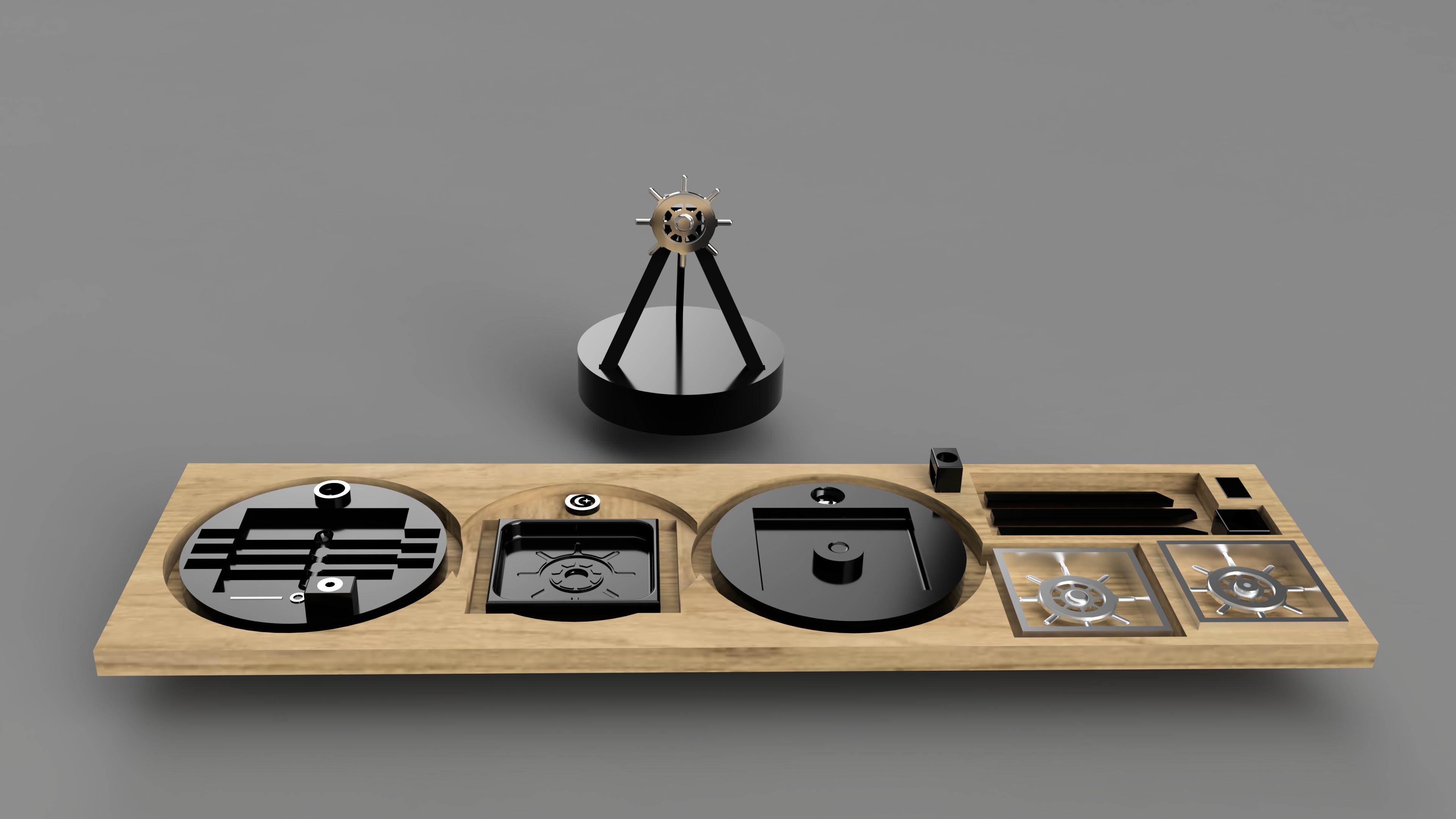
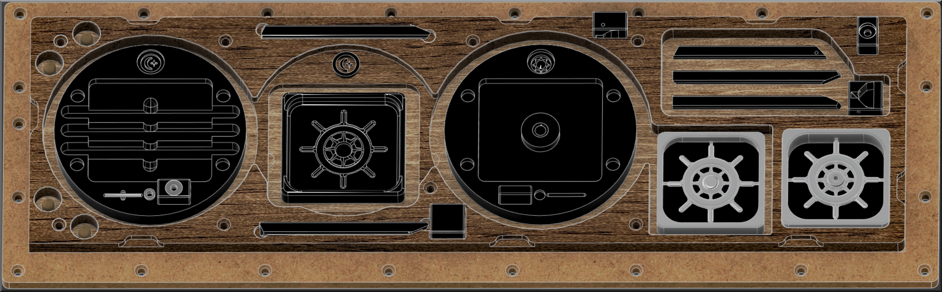
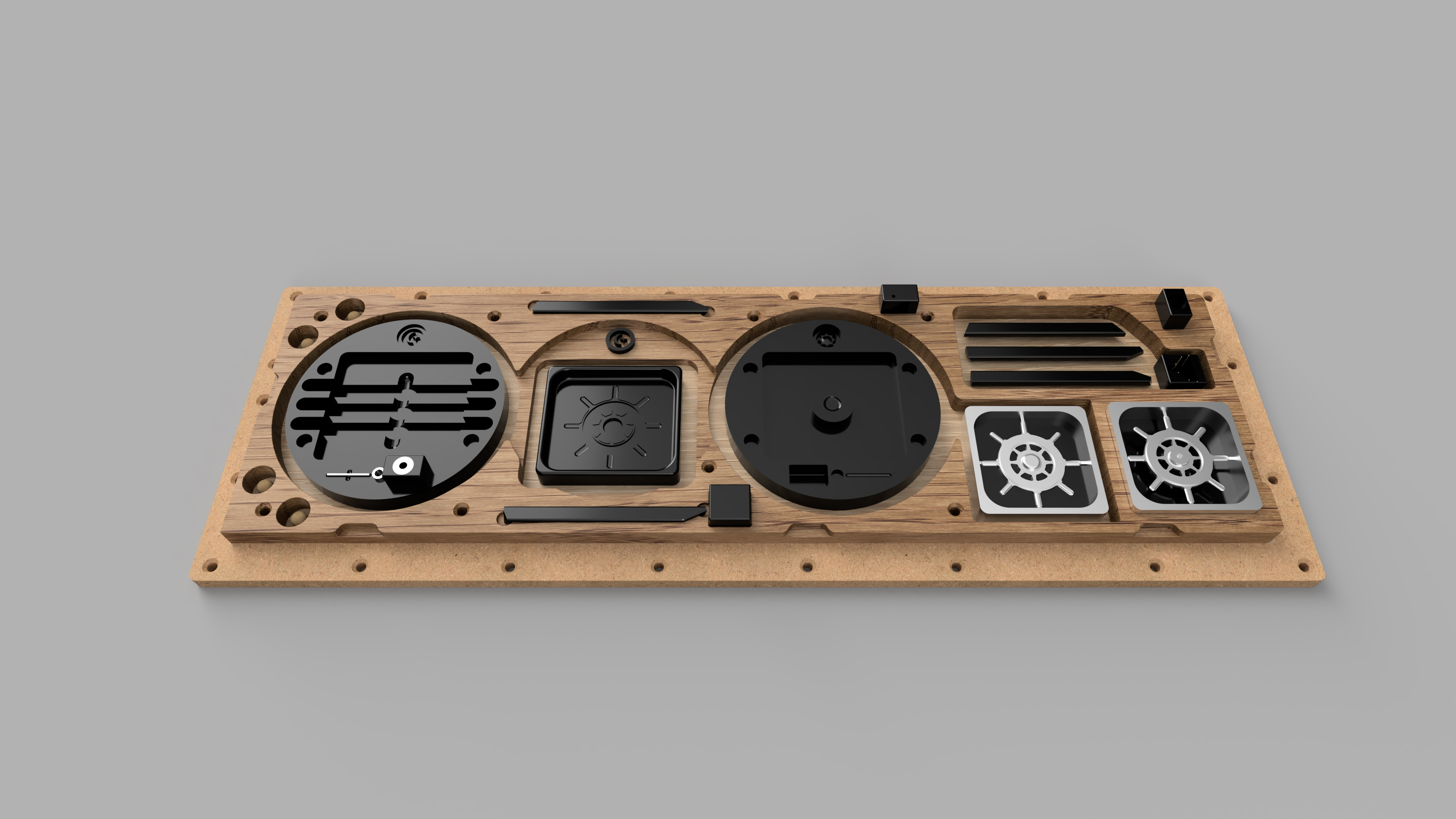
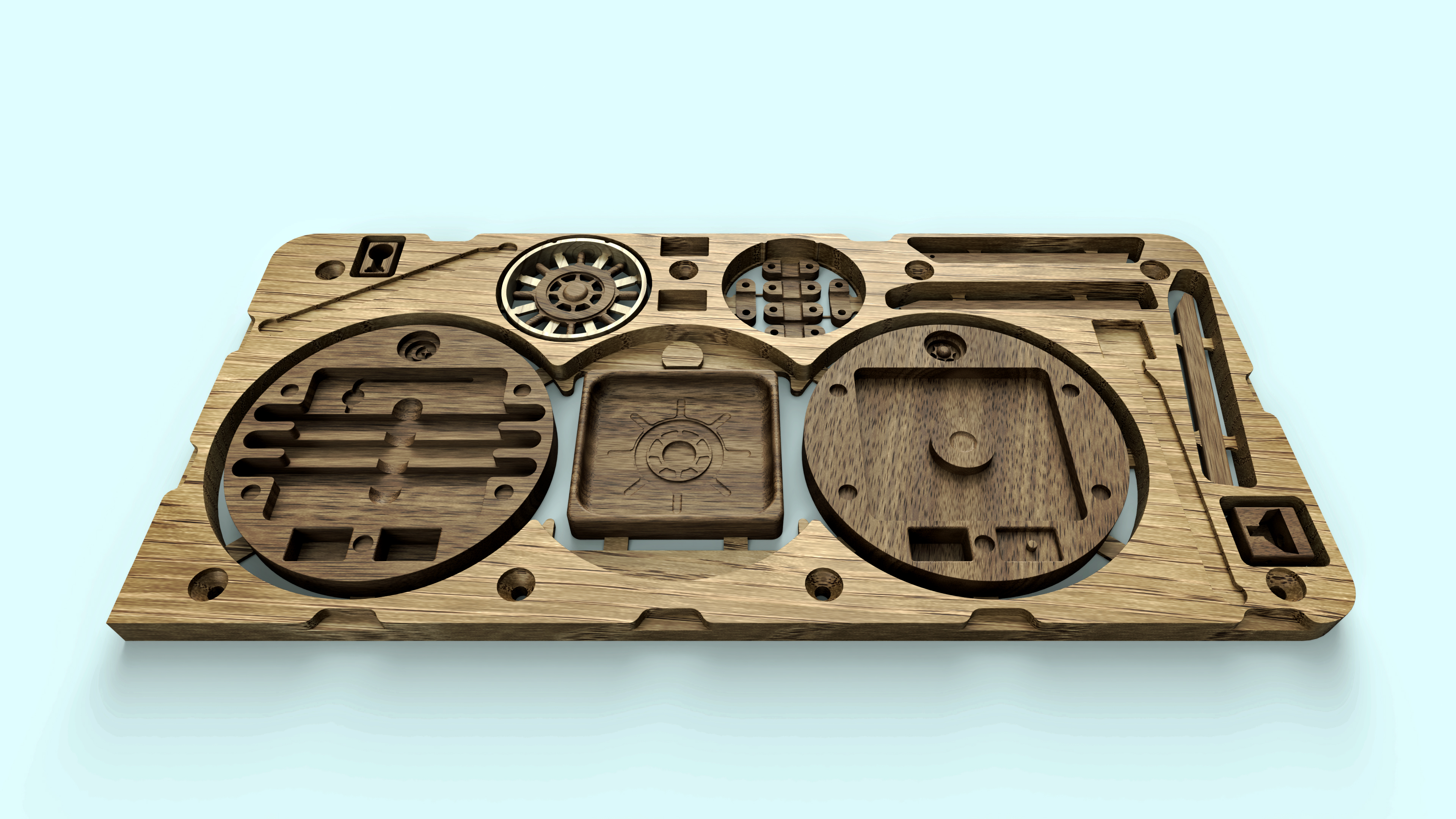
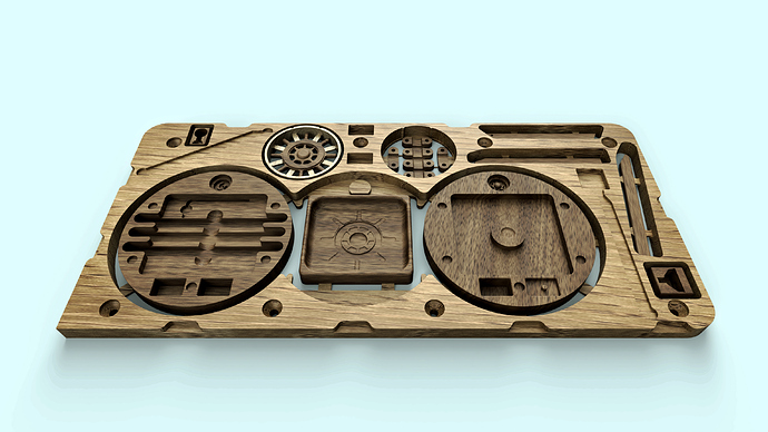
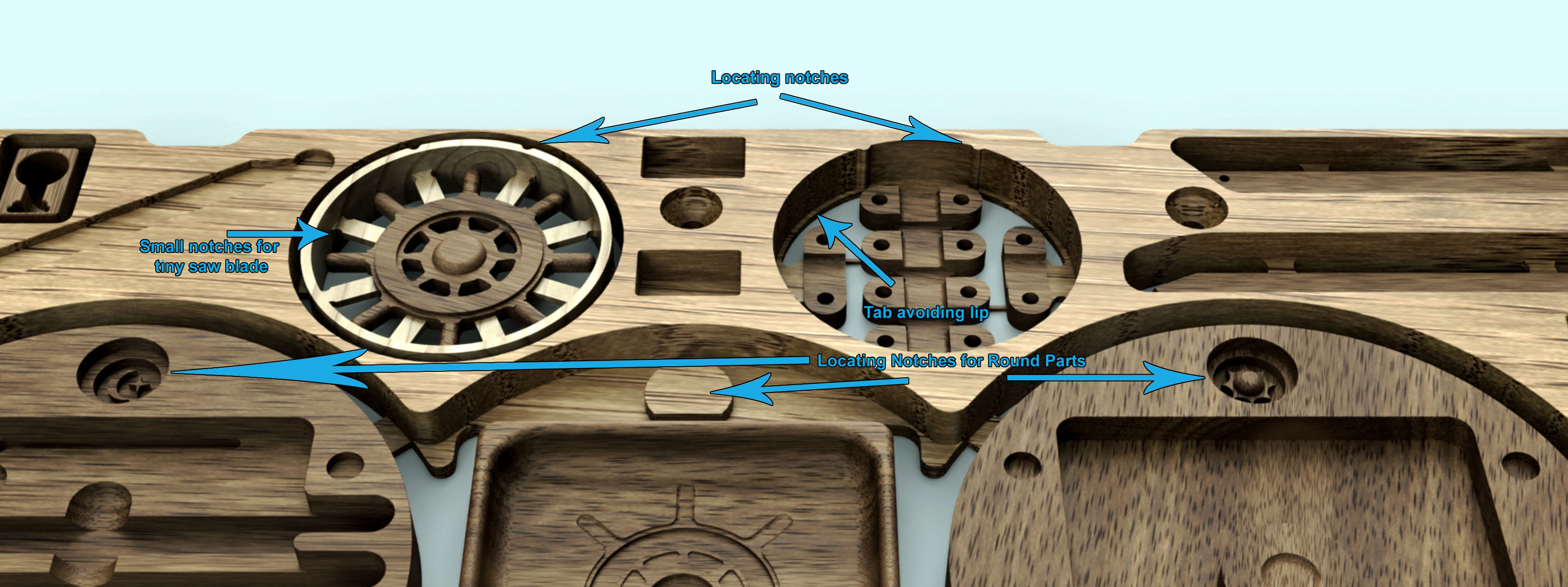
This particular project has 7 jigs built in to the board so you can perform the many two sided operations. The small square piece on the bottom right actually was a 4 sided op. The 6 small clamps are to hold down the stilts for the 2nd side ops. Once the 3 plates were removed you flip the circles over and place them in the center jig for the 2nd side carvings. The circle housing the 6 small brackets doubles as a jig for the second side ops on the Ships Wheel.
I swear these things build themselves, I just click the buttons.
I was having fun with it anyway…
Just thought I would share this Youtube video of a level I designed for kicks, I built this battle arena a few years ago with the Unreal engine. Made all the textures myself with Photoshop. Was thinking about slicing it up and carving it out of aluminum with the Shapeoko! Max Berg Level Design
Sorry to hear you weren’t getting much response in your previous thread/s, it’s hard to carry on when it seems like no one cares! It can be a little hit and miss.
It’s odd, I have found a lot of threads lately that had not popped up before (like this one). I would definitely have commented on this one or any other threads you had documenting your process.
I’d really like to get better in Fusion360, I especially like the way you have jigs built into your boards to machine both sides. Your excellent entries into the contests proves it works well! I have successfully cut 3d parts, but no 2 sided jobs, and nothing even close to the complexity you’ve done!
Thank you very much for the kind sentiment.
There is a fine line between wanting to help and guide someone, then realizing I have been doing this for about 9 months and know far less about CNC then any expert on here haha.
I have made the transition from video game design, that I have had an interest in for the past 45 years, to CNC and 3D Printing over the last 9 months. I feel like this is a tremendous step forward for me, and I plan to continue to design and build a portfolio of products to sell that I will create.
Fusion has so much going on it can definitely be frustrating. It seems like I probably don’t know 75% of the features. I pretty much learn what I need to know to build what I want to build. If I come to a point where I am stuck I just go look on Youtube or google and 9 out of 10 times I find what I need to proceed.
The best way to get better at modeling with Fusion is practice. Get lost in a project and keep building on it, pretty soon it just becomes second nature to manipulate what you are working on and turn a idea into a real thing. Also learn your physical and digital limitations on the way and try to improve on your skill set. Attempt to design a clever idea into whatever you are working on.
Suggestion: Before you go to sleep, spend 5 minutes thinking about your current/next project as you fall asleep. When you wake up you may have some fresh inspiration.
You can pretty much build anything with a circle and a square. Shaping carving and manipulating, copying and pasting, until it turns into your vision.
These days Fusion has a really cool 3D sketch program that is very nice, I used to have to build complex structures by dragging vertices around.
I usually enter into a new project with a rough concept/defined idea in my head and build on it step by step. I try to build using curves and shapes that are familiar and pleasing to the eye. I also want to make a bunch of contrasting items fit/layer together in a visually stimulating way. I also try to build symmetricly as much as possible.
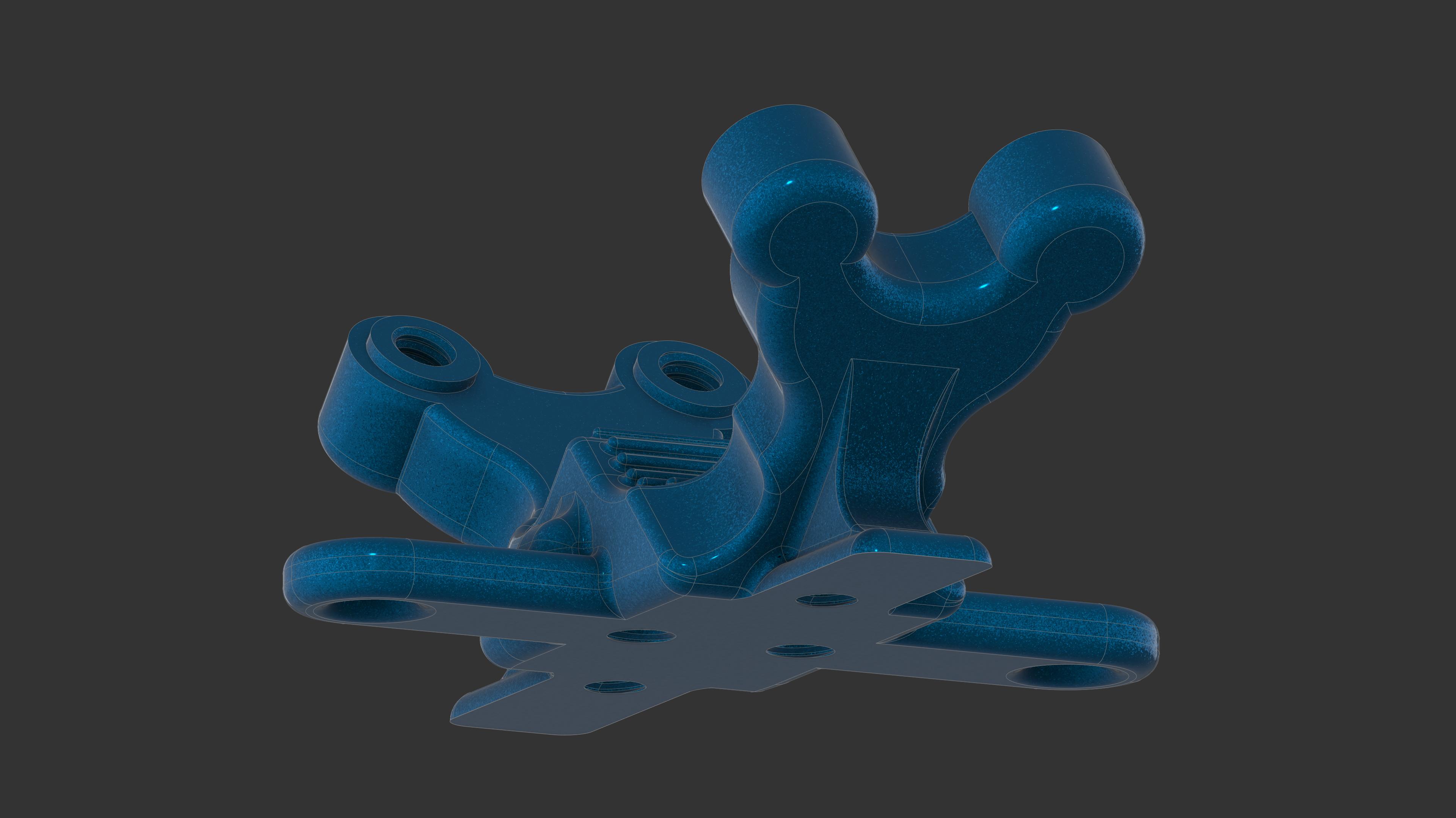
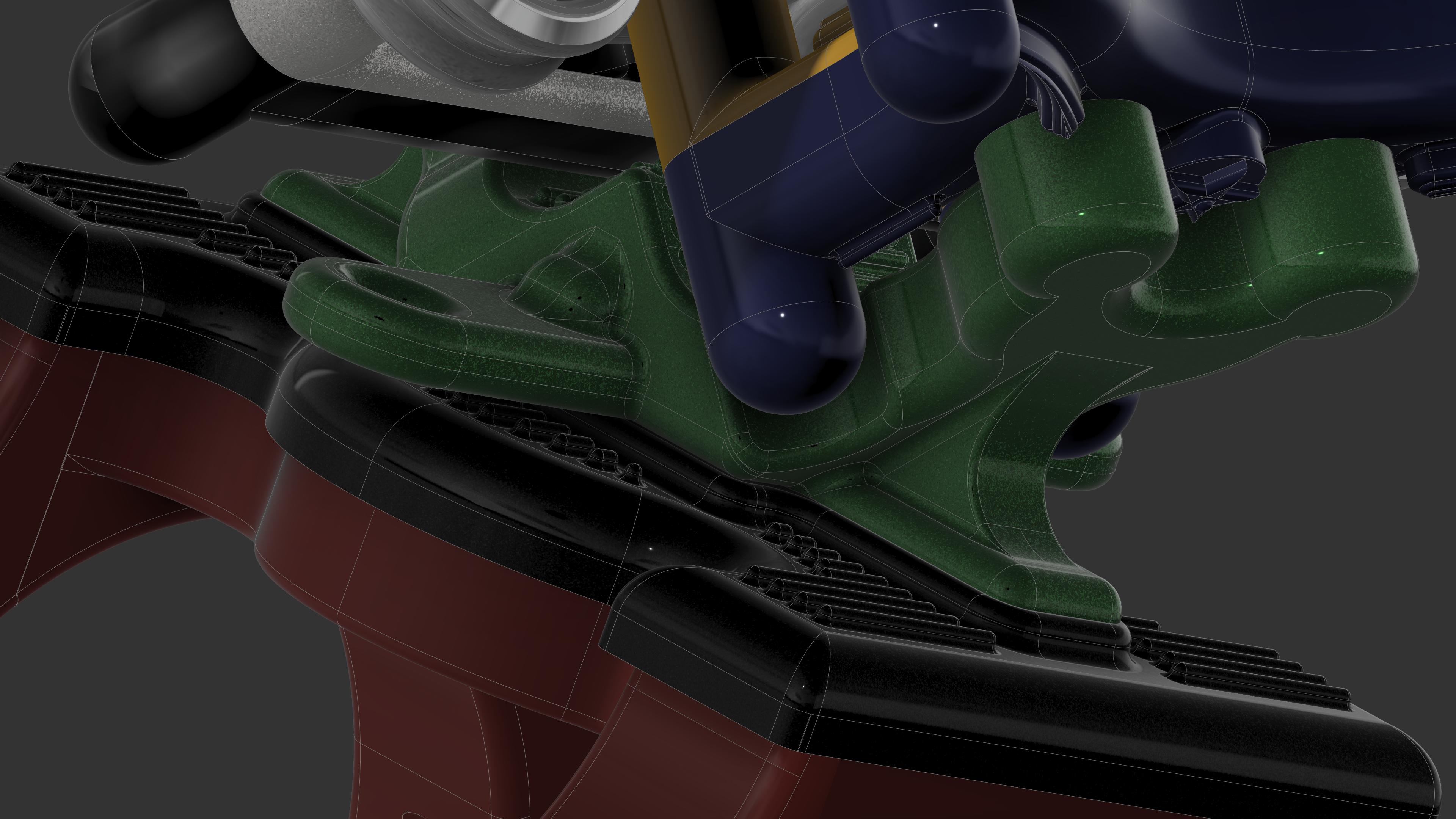
For instance, this is a part designed for 3d printing, but same principal as CNC (pic below) would function fine square and flat. However I want it to be better then that! I used a lot of circles to shape and carve this out, and tried to make it strong, functional, stylish and have many intriguing areas to look at on it. I wanted a layered structure with no square or ugly sharp shapes. It also has incorporated interlocking rings on the upper threads to help strengthen the brackets that sit on it. I also designed it so all the flat ugly parts are covered by each other and you do not see any exposed unfinished areas.
Function, strength and visual appeal. Every corner designed to be beveled and rounded. Also an attempt at clever design fitting interlocking parts together.
This is my life! Except the list of projects I think about is endless!
Thankyou for the writeup, I always like to see people’s take on using CAD.
I’m quite comfortable designing parts, for instance I would be able to create something similar to the 3D Printed part you showed above, where I’m really interested is how you design your part into the jig, like in the below project. It’s inspired me to just design a handful of smaller parts and try and work out how to replicate this type of layout
Using these jigs really relies on having your machine dialed in well. If I want two parts to slide together smoothly with no play in it, I will design for a .014-.016 gap on all sides(Depending on roughness of material). If I want a jig to weld to the part, I will give it 0 clearance and use a rubber mallet to hammer it together. The Ships Wheel has a jig built in to hold it. It is round but has 2 small notches to keep it centered. You carve out the top of the wheel, then carve out the circle jig, then place it in the jig to the right. The jig to the right has a small ledge on the bottom to keep it above the tabs height, so you chisel out the stilt brackets first, but the tab mess wont matter. You can use pieces of paper or tape to make a jig tighter if needed, apply equally on all sides to keep centered.