This would come in handy when you need to do more cutting on the surfaces that are 90 degrees from the top view. Once the top surface cuts are made you can reset the piece so its side view is now the top surface and then have your toolpaths established for the side or front surface cuts.
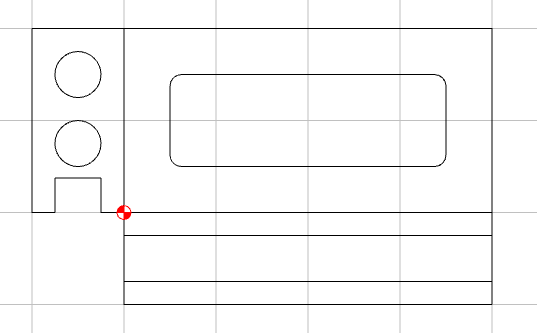
You can (kind of) do this now. It’s a 2D drawing system, so there is no 3D model for 2D machining, so you would have to draw the additional views in separately anyways.
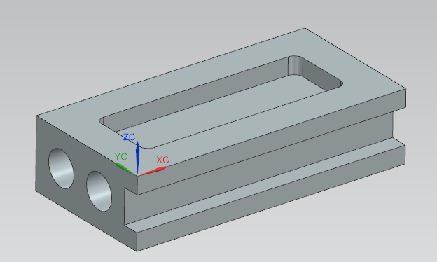
For example, if I want to draw this part
Yes. Well aware that there is numerous software out there to do this and much more. CC has all the information it needs to do this with stock thickness and vector node coordinates defined in your 2D designs. My request is for CC to be able to do this so I don’t have to go to outside software or create these views manually.
So my request to get this feature incorporated still stands.
I think it doesn’t. Each node is defined by a XY location. No Z !
There is no solid model to show a front or end view. It would just be a line / flat plane.
To do what you ask would require modifying the software to a full 3D design SW.
Even the 3D element is limited to a single direction. If I output a STL of the above model & imported it as a top view to CC, it would lose the front & side details.
I didn’t mention other software. Those you speak of use solid models (parasolids) or faceted models (STL) that are actually 3D and can be viewed in a front, side, or even isometric view.
Don’t get me wrong, I would love to use a free/cheap software that uses solid bodies. But I can’t imagine Carbide doing this as it would be an enormous amount of work.
So I pointed out that for simple designs you can do what you are asking for in CC with a little imagination and creativity.
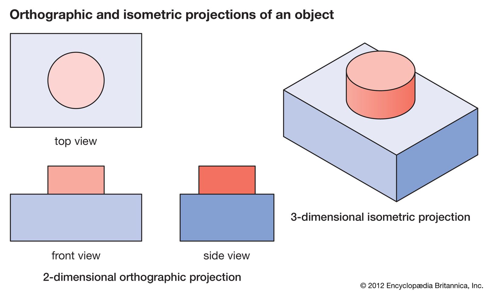
My request doesn’t ask for a solid model representation, I’m looking for the side and front projected views just like in the image in my post. It shows 2D orthographic projections of side and front views. Those are straight lines using the X and Y coordinates from the edge boundaries of the top view and the Z height taken from the job setup for the stock material thickness. In the 2D version of CC, this is a fixed value. Together this information can draw an orthogonal projection. I’m not interested in a solid model. If I wanted that, I would spend the money on 3D CAD software.
It’s just a feature request for the 2D CC. I’ll let Carbide review the request and decide if it adds value to CC. To me, it would.
Where is it getting the Z values from? In the top view in your original post you have 2 ‘features’, a base block, and a round boss. Setup defines the total height, but what defines the base & boss height?
The 3D model (in the Pro version) or the 3D preview of the toolpath — which creates the problem of how to handle ambiguous designs such as your example — @jadlp3742 could certainly be made to work, but represent a very small subset of the sort of parts which folks make.
Working up a UI which would handle all the possibilities would be a very complex problem, and any edge cases would need to be addressed in a fashion which would be amenable to tech support interactions.
For an idea of the complexity of this, see how 3D software handles creating 2D prints — I believe this is the correct set of videos for Alibre: