I have an STL of a chair seat profile that I want to carve out of a block of wood that’s 1 1/2" thick.
In Modeling, I created a Flat shape to represent the board
Then I imported the model. Obviously, if I ADD the model, it ends up above the board - not desired.
But if I SUBTRACT the model, it inverts and sinks way too low into the board
How do I go about placing the model so that it subtracts (non inverted) and aligns it’s highest edges to the top of the board?
BTW: Was there an INVERT option during STL in prior releases? I seem to remember something like that - which might have helped with the SUBTRACT option, perhaps?
If you set the origin at the top of the stock, then set up the file so that the parts of the model are within the thickness of the actual stock, and set up the toolpaths so that they never cut more deeply than the actual stock this should work — the only thing which would be lost would be some detail in the 3D preview.
That said, it should work to import the model at the original too-high thickness, check in the Design view the highest extent, then draw a rectangle the size of the entire working area and subtract that as a flat surface from everywhere to reduce the height consistently — I believe that is shown/discussed in:
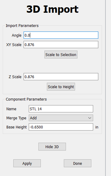
The STL files that I’m importing are smaller than the stock height…I believe. The “origin” (what is that - is it the same as Stock Thickness - Zero Height?) is set to “Top” for me already.
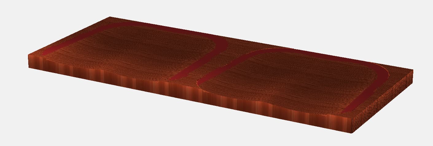
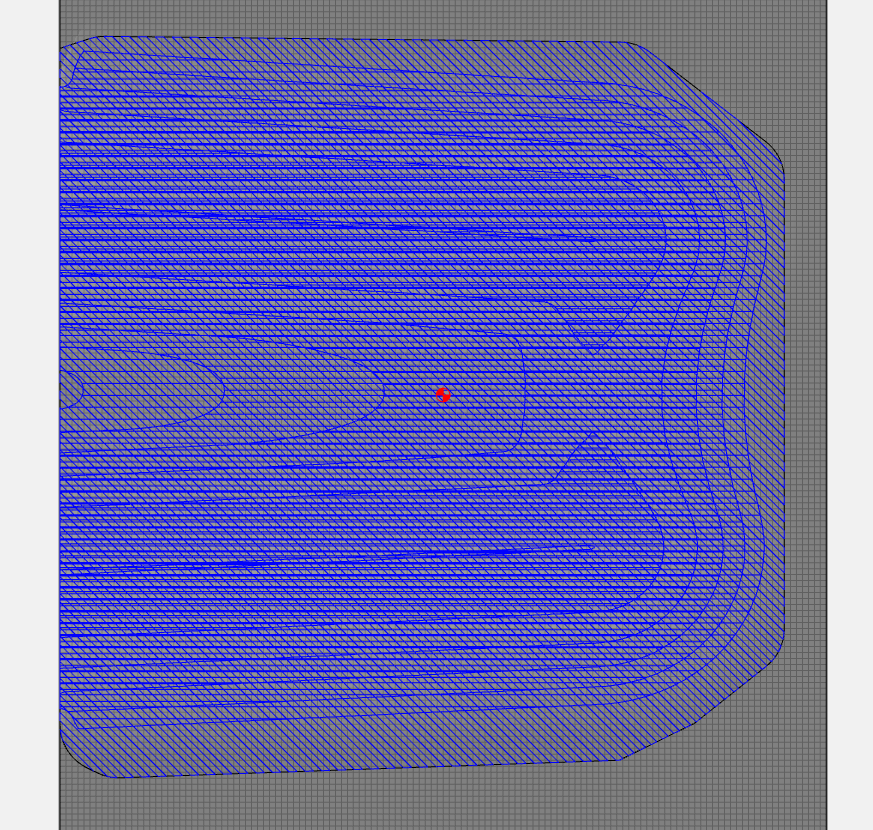
My problem is that I can’t “submerge” the imported STL into the base of stock. Add puts it above the FLAT layer, SUBTRACT inverts the model and drops it to the bottom of the base (as shown on my image above with two placed STL Imports side by side on the base made up of a FLAT 1 1/2" piece of wood.
The key was setting the BASE HEIGHT to a NEGATIVE value — effectively sinking the model into the base layer…but that can’t be the right way to do it. The result was:
I believe you can also use the EQUAL merge type which basically causes the STL to act independently of the stock & then allow you to set the Base height above the bottom of the stock until the model sits in the stock where you want it.
Next Question:
Is there a way to outline a model so that I can get a minimal bounding offset? Right now, I can only see the models rectangular bounds, but it’s a shape that I’d like to offset by a very small amount. I can’t see the boundary of the shape until I preview it, but then I can’t trace it.
I can’t upload the STL, as it is too large.
Next, Next Question:
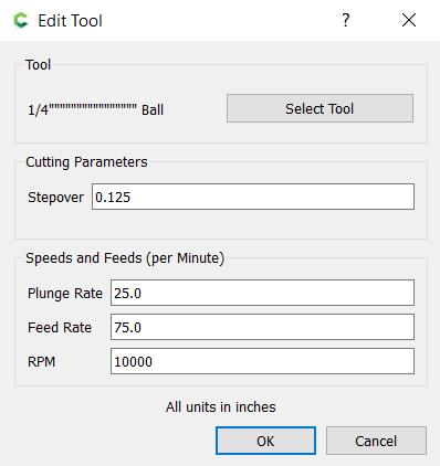
I have a 1/4" ball end bit that I’m using for the finish pass. Set like this:
The diagonal lines that are cut in the finished work are quite prevalent and defined. Not even close to being “finished”…causing a great deal of sanding to remove them. Are my settings wrong? Should I be using a different set of settings? A different bit? HELP!
Next, Next, Next Question:
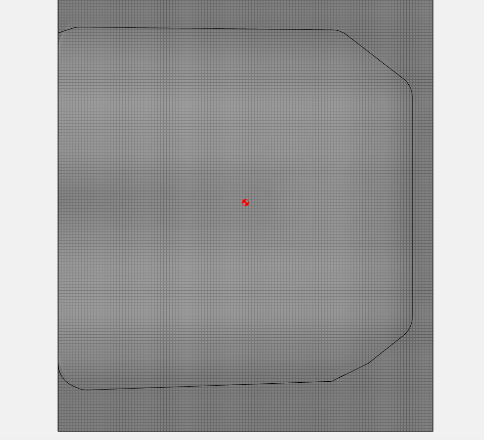
Since I can’t create a tight outline, I’ve created a bounding shape that’s larger than the modeled component. I use that shape to set up the rough and finish passes:
Here’s the issue…if you look closely, you’ll see that the FINISH toolpath fills the entire bounding shape…not just the modeled component (the curved part). The modeled shape is set ABOVE the area around it…so it shouldn’t be cut at all. For some reason, that surface around the modeled piece is cut by the ball end mill during the finish cut and leaves diagonal lines outside of the boundary of the modeled shape. Is there some way to avoid cutting those lines?
Yes, via right-click on the 3D component in the Modeling tab you can select Create Outline Vector - then enter a height value(or leave at 0 for the bottom/base of it) at which to slice thru the model to create the vector outline. From the vector you can create an outline offset vector with which to constrain the 3D Finish toolpath.
OK…so that leaves me with my last question still unanswered…
how can I get rid of the final passes lines? They are VERY defined and a PITA to sand away. Is there a way to get things actually smooth on Final pass? Are my settings / bit choice wrong?
You need a much smaller step over set for the Finish toolpath - right now it looks like 1/8th inch which is way too large. Needs to be 1/10th of that(0.0125") to really start looking smooth.
Yes, it is a tradeoff.
But with the small step over you can basically max out the feed rate. For what you’re making, you can probably find a balance at a bit larger step over that is easy enough to sand out with some testing.
You can also speed it up by using a larger ball mill. To get the same scallop height, you can use a larger stepover.
My rule of thumb for 3D, use the largest ball you can to get the detail you want. (No detail in this one, so the largest ball you have.)
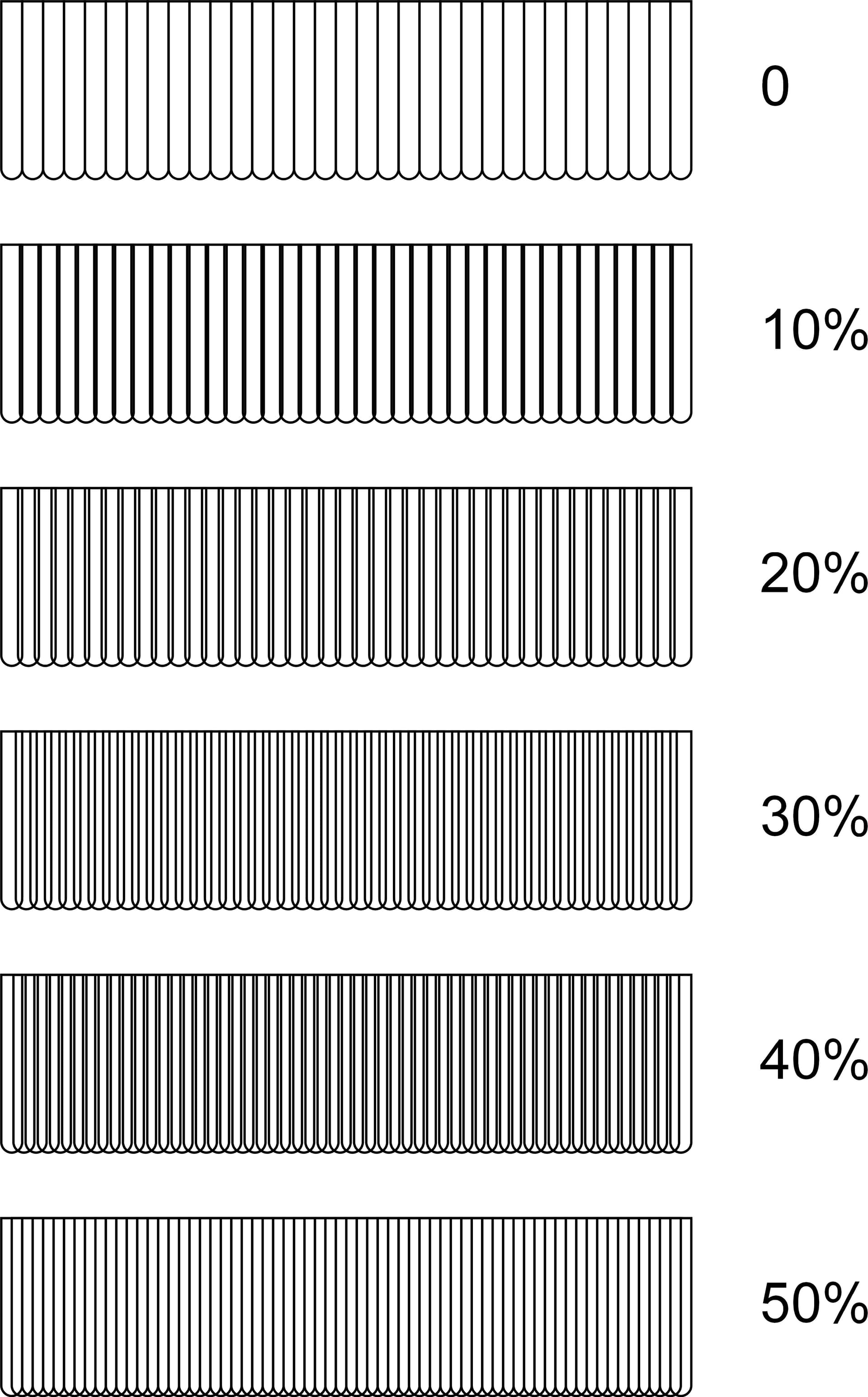
p = stepover
R = radius of cutter
h = scallop height
For a no-sand finish you’ll want a scallop height of 0.001" (0.025mm) or less.
Which works out to about a 0.045" stepover for your 1/2" ball (Not roundover, that’s concave)
That’s 9% of tool dia. The “rule of thumb” being 8-10%