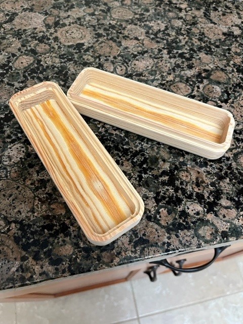
Figured I would try out making a routed box. The pocket is leaving a thin sliver in the center. Is there a setting I missed? Looks pretty thin so probably not a big deal to clean up.
John
`
Figured I would try out making a routed box. The pocket is leaving a thin sliver in the center. Is there a setting I missed? Looks pretty thin so probably not a big deal to clean up.
John
`
This can be fixed w/ a quick pass w/ a sharp chisel.
To keep it from happening in the future, adjust the stepover so that there isn’t a broad gap in the center of the pocket.
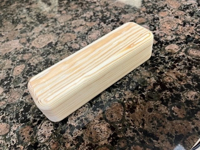
It was only 0.009" , So a quick flick of a finger and it was gone. Very slight ridge was left.
Box came out pretty well. On the design started from the pocket outward, making the inside corner larger than the cutter radius. Then used the parallel path tool, working outward. No fussing with angles since I set the radius of the smallest turn larger than the cutter.
Any suggestions on speeding up clearing out that big of a pocket? I also need to look into longer mills.
John
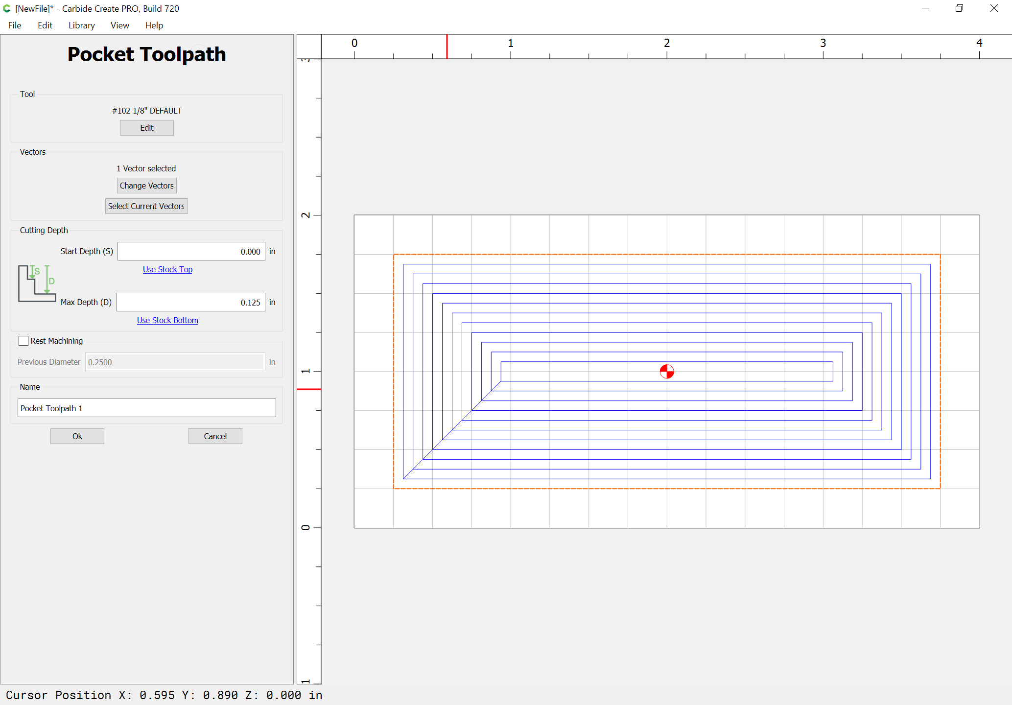
@WillAdams I have to admit I don’t normally use CC (fusion 360) and I saw this yesterday as well. I was confused. I used the default settings for the #201 end mill and it did this. I would expect the pocket to cut one long full width (1/4") pass across the stock to establish the first cut and then to step over the step over amount (1/8"). However, it looks like it instead does the one long full width (1/4") pass across the stock and then back at at another 1/4" full width pass before starting to cut at 1/8" overlaps which was the default stepover.
How would changing the stepover fix that? Or how do I understand how the stepover is causing it to move over double the stepover amount on the return pass?
Sometimes, in a CAM tool, the stepover for an endmill will result in the central pass just barely meeting in the center, resulting in an area which is wider than others when viewed in the CAM tool:
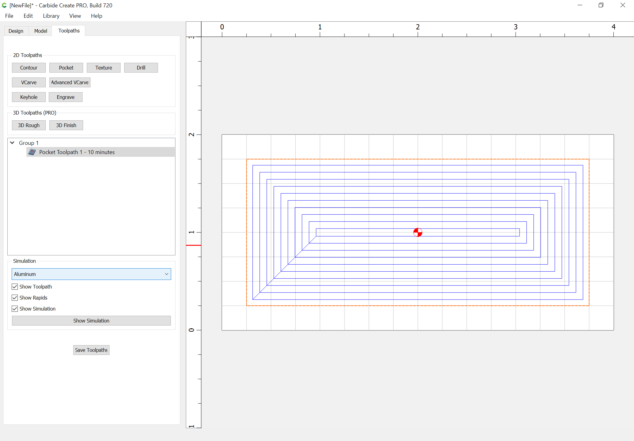
Adjusting the stepover allows one to arrive at:
What are the two stepover values you used? It looks to me like the first toolpath does 11 loops and misses in the middle (unless the tool is exactly the nominal diameter) and the second looks good but only does 10 loops to complete the pocket even though the first two passes are closer together?
0.062 and 0.072
Probably smaller steps which increase the number of passes would have been better.
Um, am I being dense? You increased the stepover and it would remove the uncut seam in the middle?
Yes, changing the stepover in either direction will alter where the center falls.
I guess what I would expect is that if:
then the next pass from right to left would be at y=05, but it appears that isn’t the case? If so, how is that first right to left distance determined? Is it related to the size of the pocket relative to the stepover?
I just realized I still have the gcode sitting around for the job I ran. I was using a #201 (6.35mm) with the default stepover (3.175mm) and the first pass was
(PREPOSITION FOR RAPID PLUNGE)
G0X34.925Y34.925
Z26.543
G1Z22.987F381.0
Y41.275F1905.0
X269.874
and then the return was:
Y34.925
X34.925
which means that the first 2 passes were 41.275-34.925=6.35mm apart even though the stepover was supposed to 3.175mm.
The next pass was what you’d expect at Y31.750.
The problem is the machine makes one pass at 3.175 stepover, and that gap lines up w/ the gap from the other pass on the other side.
Does this mean that you can’t do a stepover > 50% without leaving an uncut section in the middle? That the first two passes are 2xSTEPOVER apart?
This behaviour isn’t what I was expecting. I was expecting the first pass across the pocket to be the zero point and then the next passes to be a stepover apart. Instead, it sounds like the zero line is the zero line and the first pass is -STEPOVER from the zero and the second pass is +STEPOVER from the zero. Is the correct?
No, it means that for certain sizes of pockets, certain stepovers will result in a larger uncut area at the center.
Sorry to be a pain in the butt here, but I really am trying to understand because I will likely end up using CC more over the summer for the v carving…
To me, this feels like a bug. If I ask for my passes to be X units apart then I would expect each and every Y to be X units off from each other. If the pocket size is not a evenly divisible multiple of X then I would the passes that account for the discrepancy to be smaller than X, not larger than X.
When this happens, I can always clean it up, but it just sounds wrong to me.
To illustrate why it seems wrong, if I set a stepover of 0.235" (which should be fine, but maybe stupid, for a 0.250" endmill), I get the first two passes at:
Y33.020
Y43.180
which is a difference of slightly more than 10mm meaning a gap between the two passes of 0.4" even though my stepover was within what I would expect to be a valid range.
It’s an interaction between the size of the pocket, and the accumulation of the stepover passes — experiment w/ it in Carbide Create — the step-over is easier to see if you use a ball-nosed endmill.
Yes, that’s what I’m seeing (there is an interaction between stepover and pocket size) which is what I am finding to be surprising. Let me try once more to rephrase.
If my stepover is SO then if I take any two Y values from the passes across the stock, I expect the difference between them to be less than SO. In the example I just cited, I see a SO=0.235 and a /\Y = 0.4 which cannot possibly clear all the stock even though the stepover is less than the endmill diameter.
Correct, except at the center — it’s possible there for the gap to be somewhere between SO and SO * 2 — it’s that which stepover changes.
Chris,
I want to preface this with the fact that I have not used CC, but have used other software for producing CNC G-code. 2nd, as a rule of thumb I generally do NOT use a step-over value greater than 75%-80% of the actual tool diameter (as measured by me, not the theoretical size specified by the manufacture).
I think what you are doing (based on my understanding) is starting a contour mill operation in the center. Unfortunately the calculations for such an operation (in my experience) are from the outside in. So what you are calling the 1st step is the last calculated contour and the distance between them will nearly never equal the stepover value given (unless the moon aligns with saturn on the third full moon of a leap year ;). The center “step” value will range from > 0 to either 2x SO (as Will said, so I assume that is how CC does it) or 2x the tool radius of the tool you are using (based on the value in the software - this is what I believe I have seen with AlphaCAM). Tool definitions in the software are not always “exact” for the tool and if the tool is even slightly undersized the possibility of an island increase. Same if the profile of the tool is not a perfectly sharp corner (some tools have a slight radius where the bottom transitions to the side). In your case per Will’s comment, 0.4 is < 2*0.235 and as far as CC is concerned (theoretically) there shouldn’t be a gap.
I myself had an issue where a replacement tool was different size. Our machine using something called tool compensation, which works on machining a contour, but not a pocket (ie an outside edge operation). If this scenario you have the tool parameters in the machine (in this case a Siemens controller). HOWEVER when you do a pocket operation is use the values in the software (AlphaCam in this case) to calculate the path. As I had changed the tool parameters in the machine (Siemens software), but not in AlphaCam, I had some issues that I didn’t realize until later.
I hope this somewhat long, possibly over detailed, explanation (based on my experience with AlphaCam) helps clarify things on how “contour” pocket operations (not spiral or linear pockets) work and are calculated. I apologize if it’s “TMI”, but based on what I read, you and Will were not on the same page (or same paragraph of same page at least).