Don’t know if it is a bug, but that is exactly what is happening with the cuts.
All you need to do is… ![]()
(not really) But my suggestion would be start with something REALLY simple like a rectangle or a circle to get it dialed in, and on some cheap wood like a 1x4. That way you can whip out some basic shapes to evaluate the details of the interlock, before going for a full blown lion or text. I think you will get it and be successful.
-Christian
2 Likes
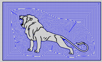
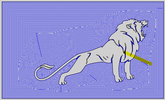
It Looks Like in the picture that the lionis very little and istoo small to cutThe fuzzyes you see are a factor of using the wrong bit or drll bit .It also needs to have a wood sealer put on the board before cutting . Also try something a litter bigger for your first try Also see if you can find a inlay file that is all ready created in CC and buy it if you can ang get the hang the way it was designed and toolpaths set and tool use setting up the G .
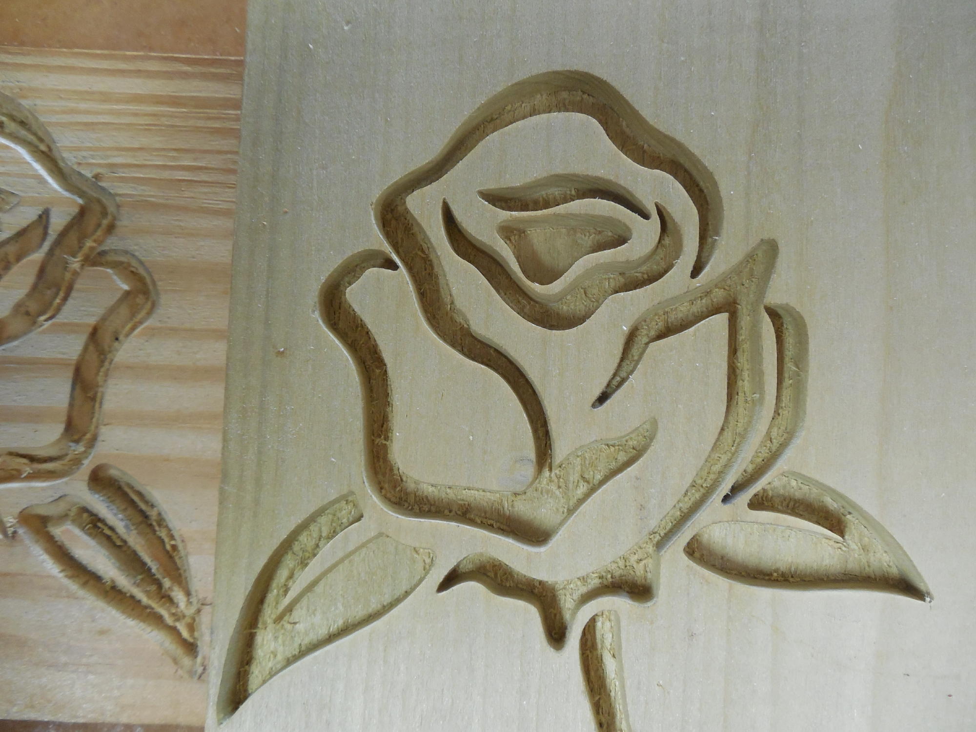
I am going to suggest another thing have you tested the Z axis for its exact movements. If it is not moving to the exact distance you male and female cuts will not be the same. Some thing else do simple inlays for testing like a square this will tell you very quickly if the depths are correct and if you are using the correct start depths. Do the cutting and glue up and then cut them in half to see how things look.
this is a good video on depth checking.


1 Like
Appreciate the input.
I have cut a few squares and circles and the seem to inlay fine. As for the measurements you use with VCarve, how do you see them translating into CCreate?
I really don’t want to have to purchase VCarve just to do these.
Thanks
Also thinking outside the box … where did the lion graphic come from?
Was it made especially for CNC or a 3D printer BY SOMEONE who understands the differences?
Or perhaps just a graphic designer who only understands graphics for paper output?
Also, how about this to test. Grab some MDF or Hardboard. Scale up the lion graphic to 5-7”, add use a 60VB and standard CC F/S parameters (if I remember correctly, they are really conservative F/S).
How’s it look? If it looks good, scale it down again. Repeat.
Looks bad at first? Scale up and repeat.
Carbide & all their products have been around too long, with I’m sure hundreds, if not thousands of successful inlay projects in the wild.
It’s going to come down to hardware, software, or user error (what I normally do🤔) so let’s narrow it down to one of these.
Frustrating? Absolutely. Solvable? Also absolutely.
1 Like
Appreciate the outside the box thinking. I have no problem thinking it’s operator error, but so far all attempts to solve have not been successful, even to the point to where I have given up on doing inlays at this stage.
Pick up a copy of F-Engrave and go through his process.
This may be totally wrong. I’ve done quite a bit of straight (vertical edge) inlay work by hand and by routing, always cutting to a constant floor depth (the veneer thickness minus a sanding margin).
I’ve always assumed the purpose of using a V-bit to perform the cutout was to do the same task, but with an inwardly tapered edge to make it easier to get a tight fit and increase tolerances a little. However, to reach that floor with a V-bit, the minimum width of the cut at the work surface has to be at least 2 * tan (bit angle/2) * depth. For a 60 degree V-bit, that’s about 1.2 times the depth from the surface to the floor. Anything less than that will not reach the floor and it won’t result in a full-thickness inlay (down to the glue-gap).
It looks like the inlay mode toolpaths that are in Tod’s post are respecting this, cutting only those lines where the bit will reach the floor (while the straight V-carve doesn’t care if they don’t). You’ll soon tell if you scale the lion up gradually a few times and watch the narrower valleys start to be machined as they reach critical width.

1 Like
This topic was automatically closed 30 days after the last reply. New replies are no longer allowed.