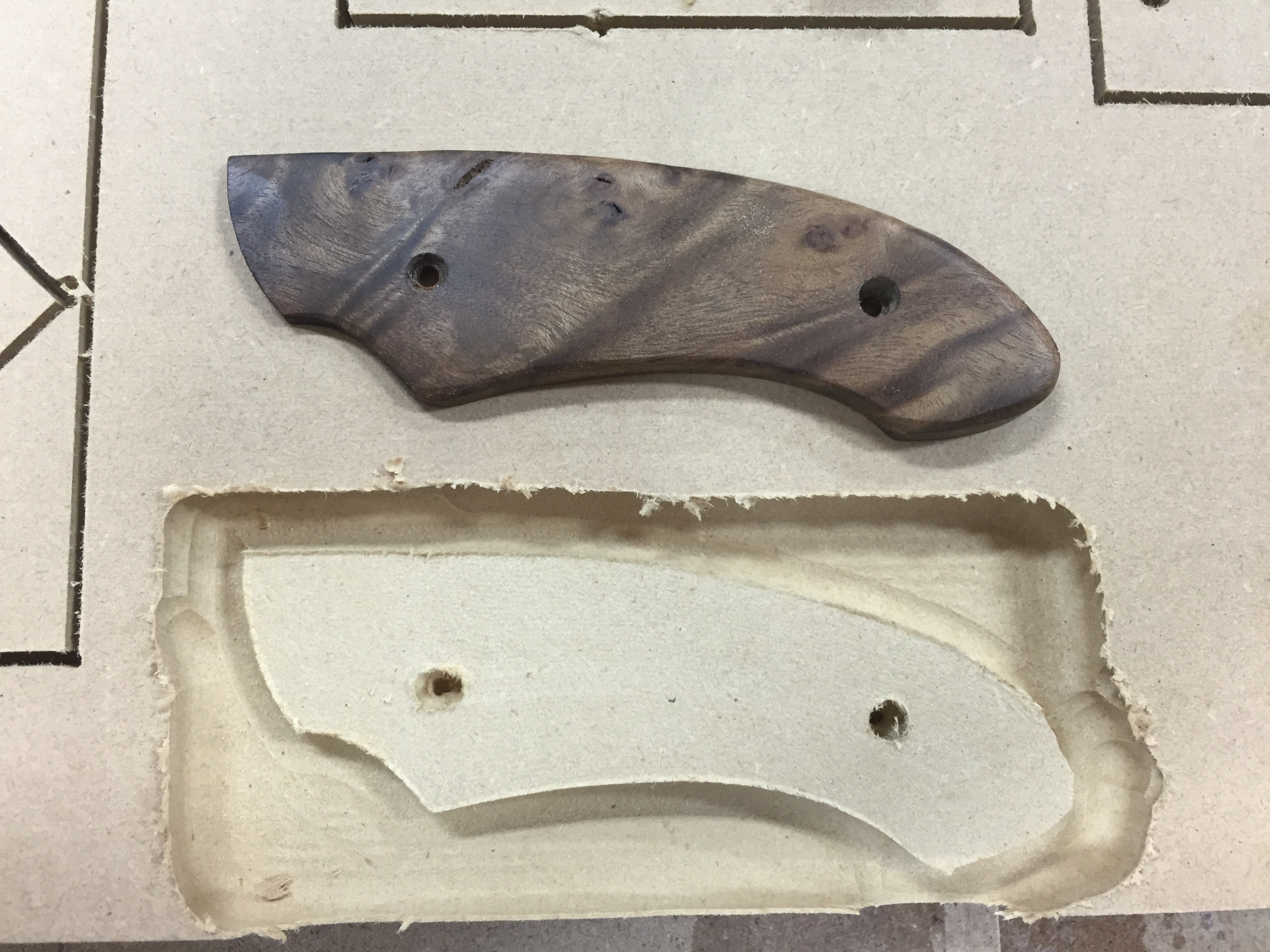
I am in the process of trying to figure out how to go about making some knife scales. I am using MDF for prototyping and have it really close to being right with one exception in particular. I built this in Fusion 360 and broke it up into two jobs…one for the 1/4" ball end mill and one for the 1/16" ball end mill. I ran both thru CM. The first one seems to have run fine (a couple of odd profile anomalies are noticed on the RH side) but it is the small counterbores that are horrible. Any idea what would cause this sort of crappy result? I have reviewed the toolpaths at length, all seems well. Is it due to some slop in the gantry or something?
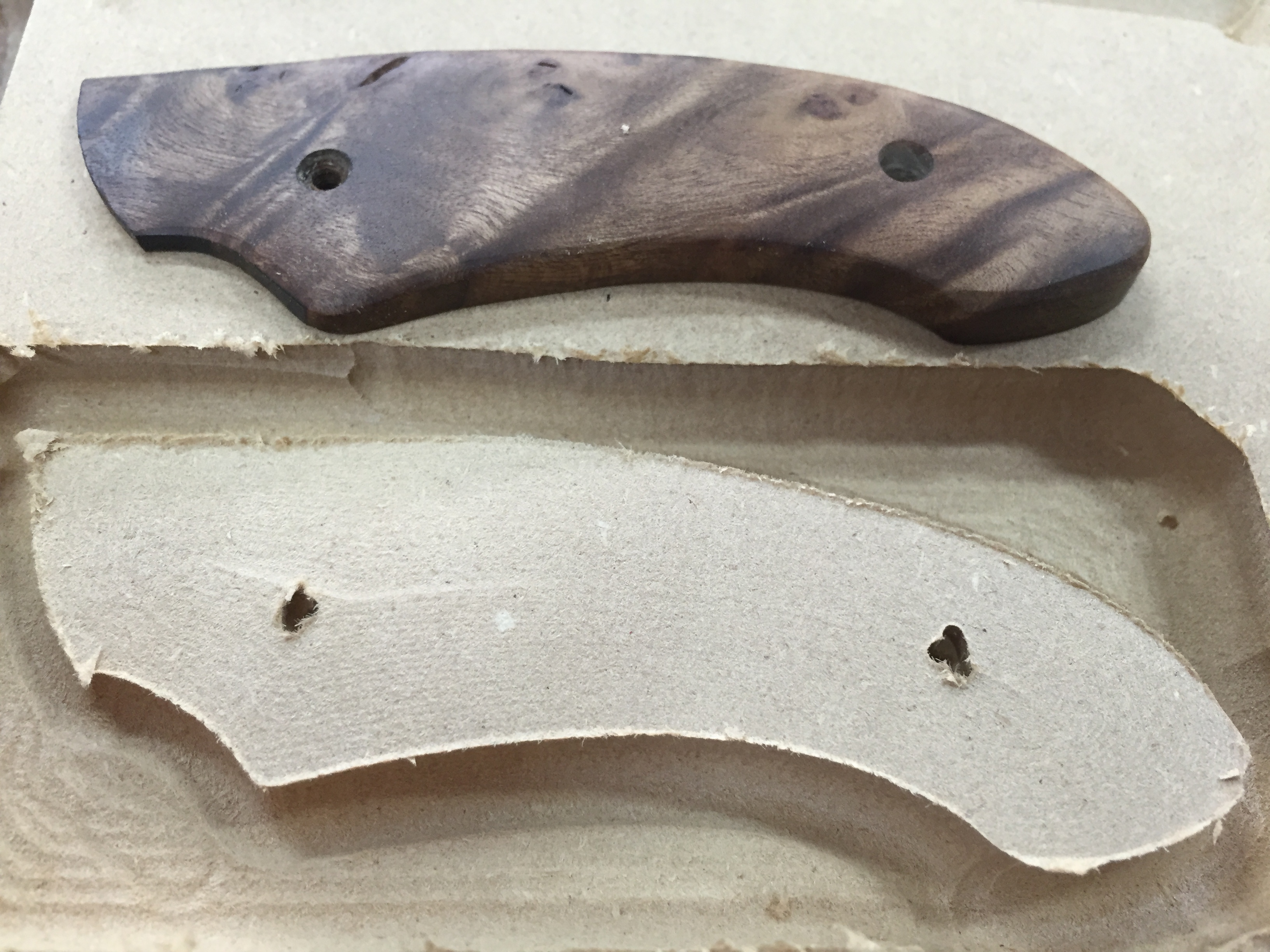
Tightened up the belts, seems they have stretched a bit since initial install which has only been a week. Helped quite a bit. However, the bores are a bit undersized even though I have calibrated the machine by adjusting the X and Y steps. Maybe need to do it more, not sure what else to do to ensure accurate features.
Your counterbores look exactly like the counterbores my machine was making when I made a ‘sea of holes’ mounting board. My problem was that the set screws on my y-axis motors were extremely loose. The machine was able to locate itself with accuracy and handle ‘low-load’ operations really well but the counterbores were enough to make the pulleys on the motor shafts slip. It made some weird shapes.
Tom
2 Likes
Yup, as it turned out, mine needed to be tightened up too. They were not loose as you’d think, just not as tight as they needed to be. Since those set screws are so small and into aluminum, I was afraid to overdo it, ya know?
Chris,
But did you put one on the motor shaft flat? Because if you didn’t it will spin again in the future, guaranteed.
Yes. All were already oriented on the flats, just not tight enough. Checked and rechecked 
1 Like
FWIW, I put blue lock-tite on mine when I tightened them.
Tom