SO3 on steroids - build log

Hmmm I have two routers so if I wanted to upgrade them both at the same time it would cost fortune so it’ll have to wait unfortunately. What sender are you using? Heard Streamdeck is awesome with UGS but I’m using CNC js and really not looking forward to going back to ugs.

I have been using both ugs and cncjs with new streamdeck
My go to is ugs

:open_mouth::open_mouth::open_mouth:

is that a ROCKET on the ceiling…?
(also, you probably just won 1st prize for the nicest and most expensive Shapeoko setup out there :slight_smile: )

3 Likes

Where do you keep yours? You don’t want to always be tripping on the thing.
:grinning:

1 Like

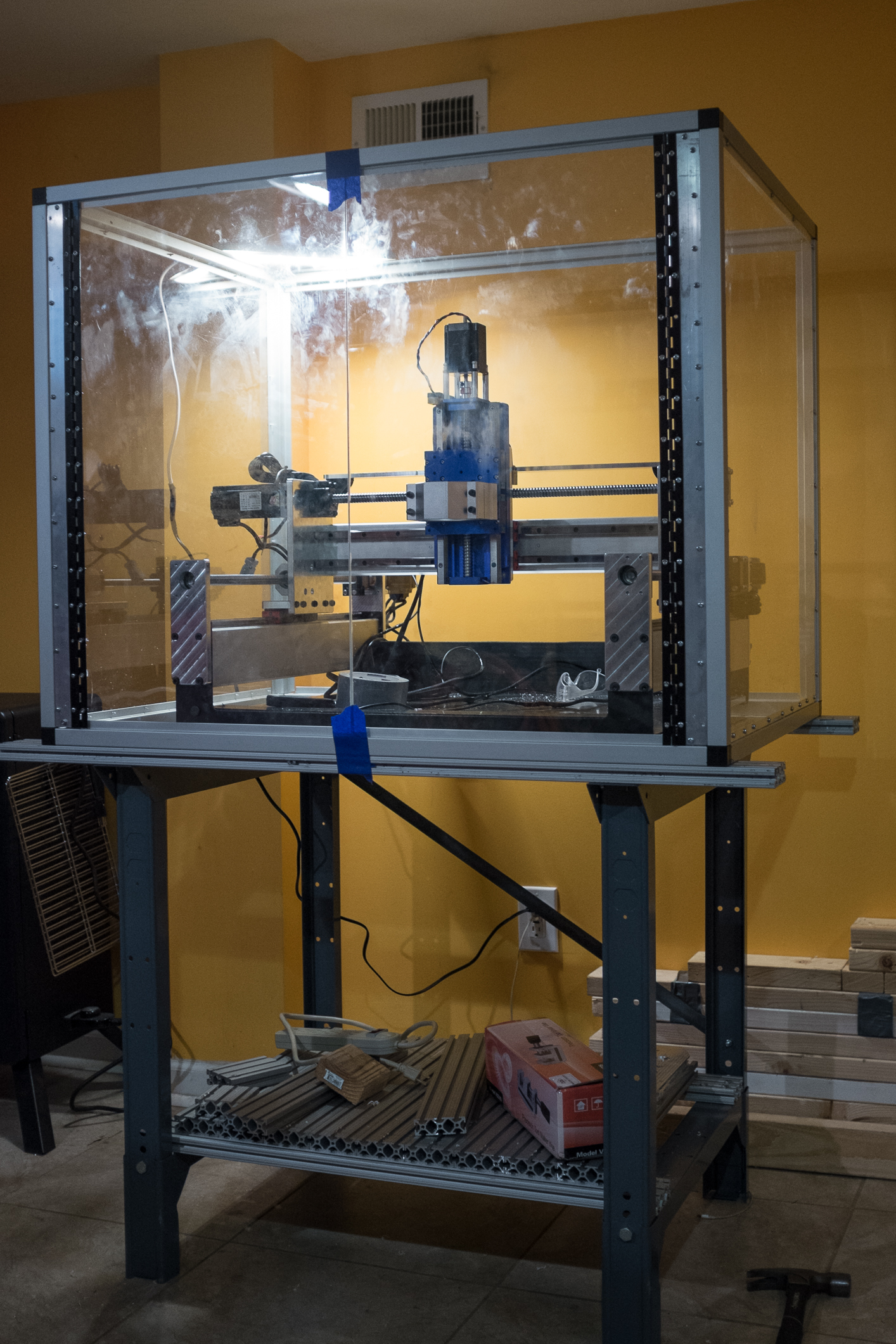
Spent last couple days finishing up the enclosure and adding some small bits to the machine, so while the progress might not seem significant, all that ‘little’ stuff had to be done and was rather time consuming.

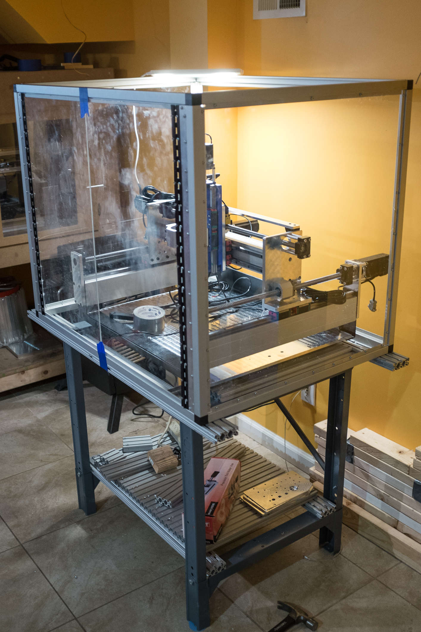
First of all, added plastic panels to the enclosure at the front and sides. Front doors need some adjustment and handles :smiley: I’m going to get neodymium magnets and 3d print some brackets to use as a magnetic door latch. Top part of the enclosure will be made out of white corrugated plastic as well as the back. The enclosure was designed in such way that the motors will be sticking out in the back. Still haven’t figured out what to do about the bottom part. Like I mentioned before it would be ideal to have some kind of hopper that would move chips into a bucket, but I haven’t figured out how to make it yet to be cheap, simple and least time consuming.

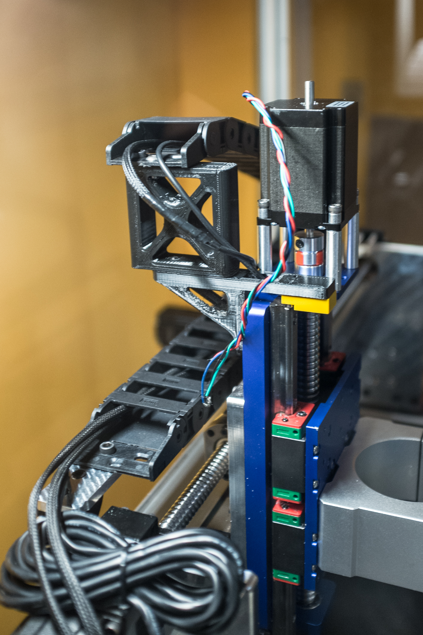
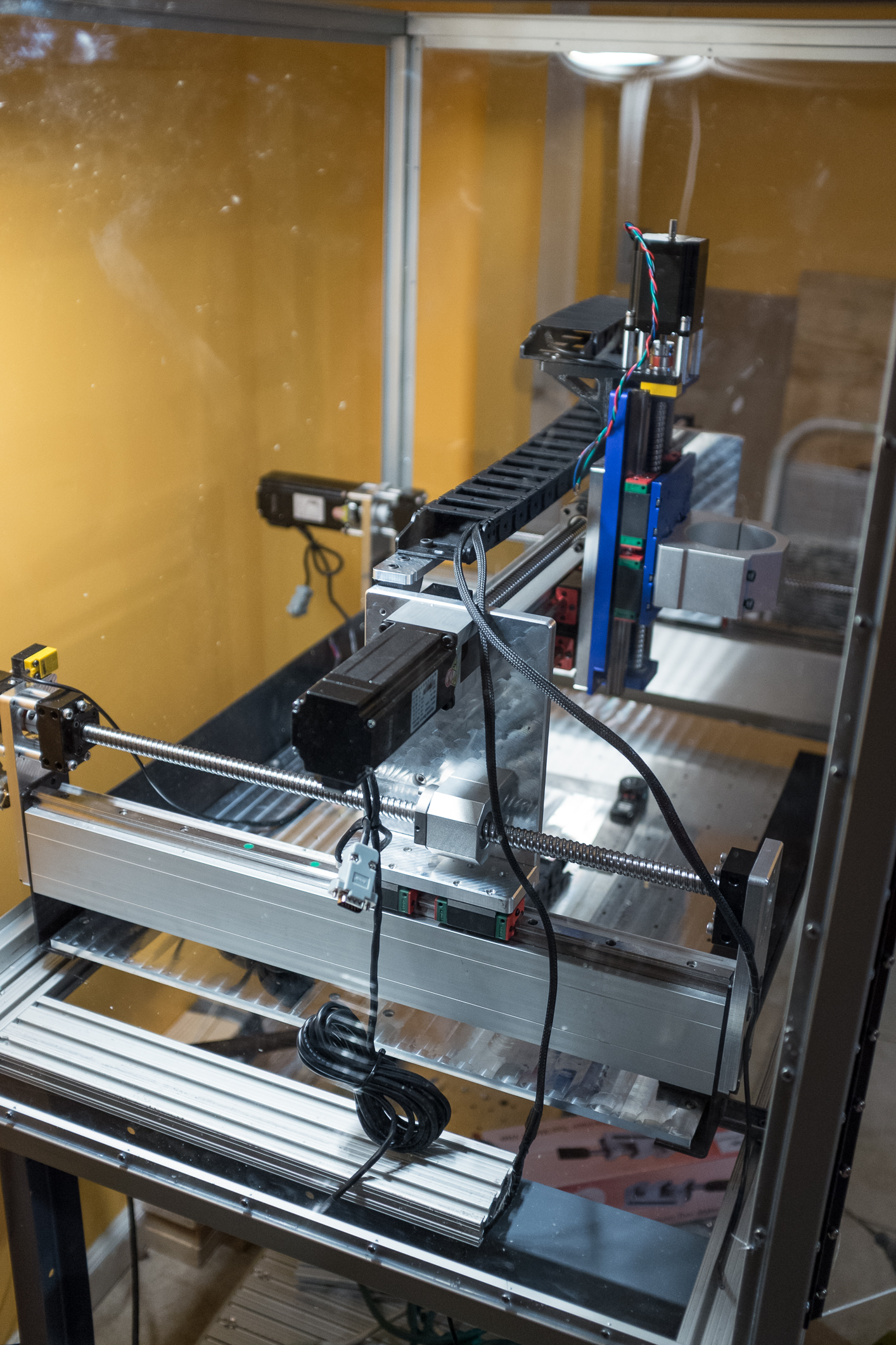
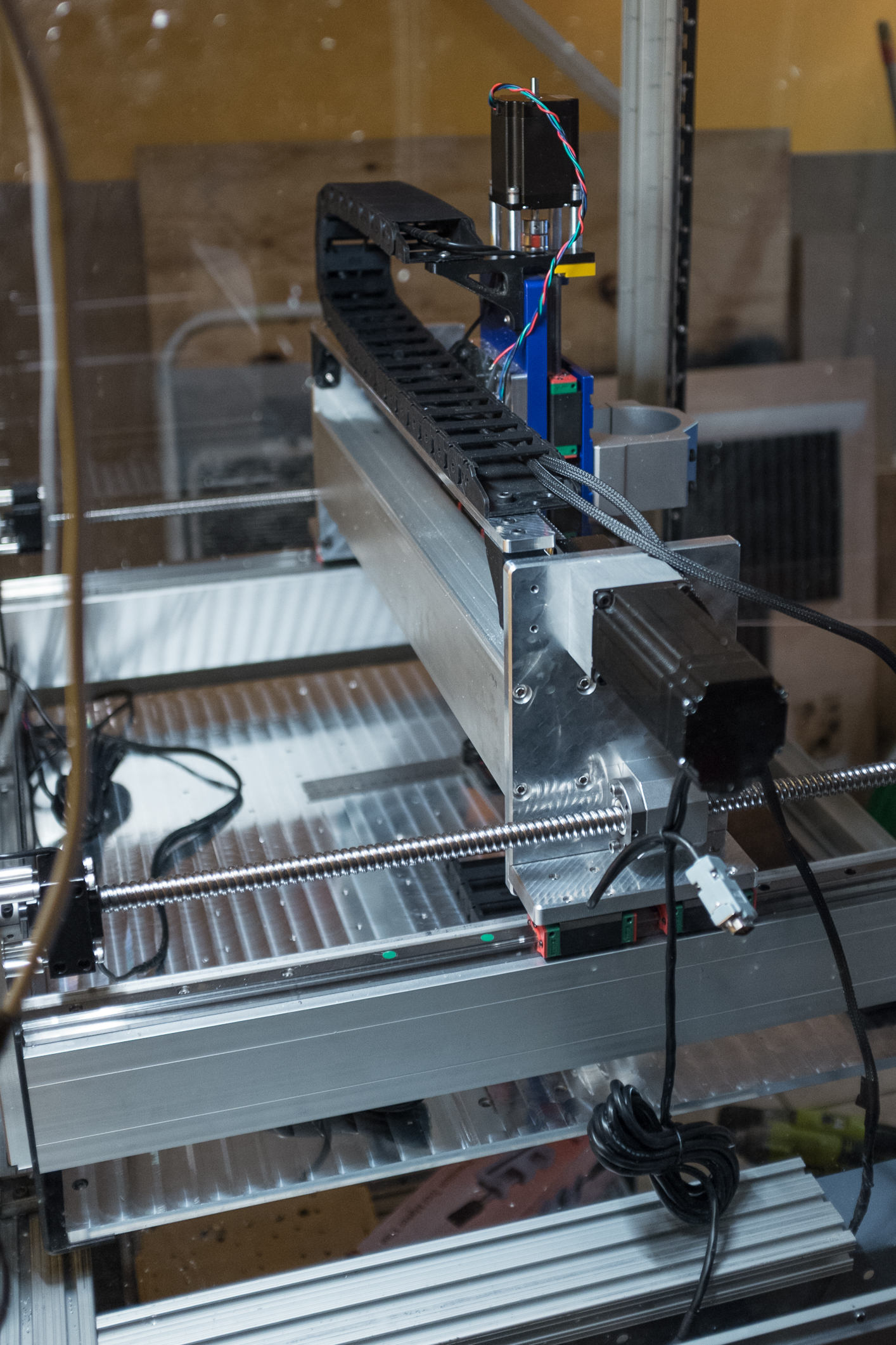
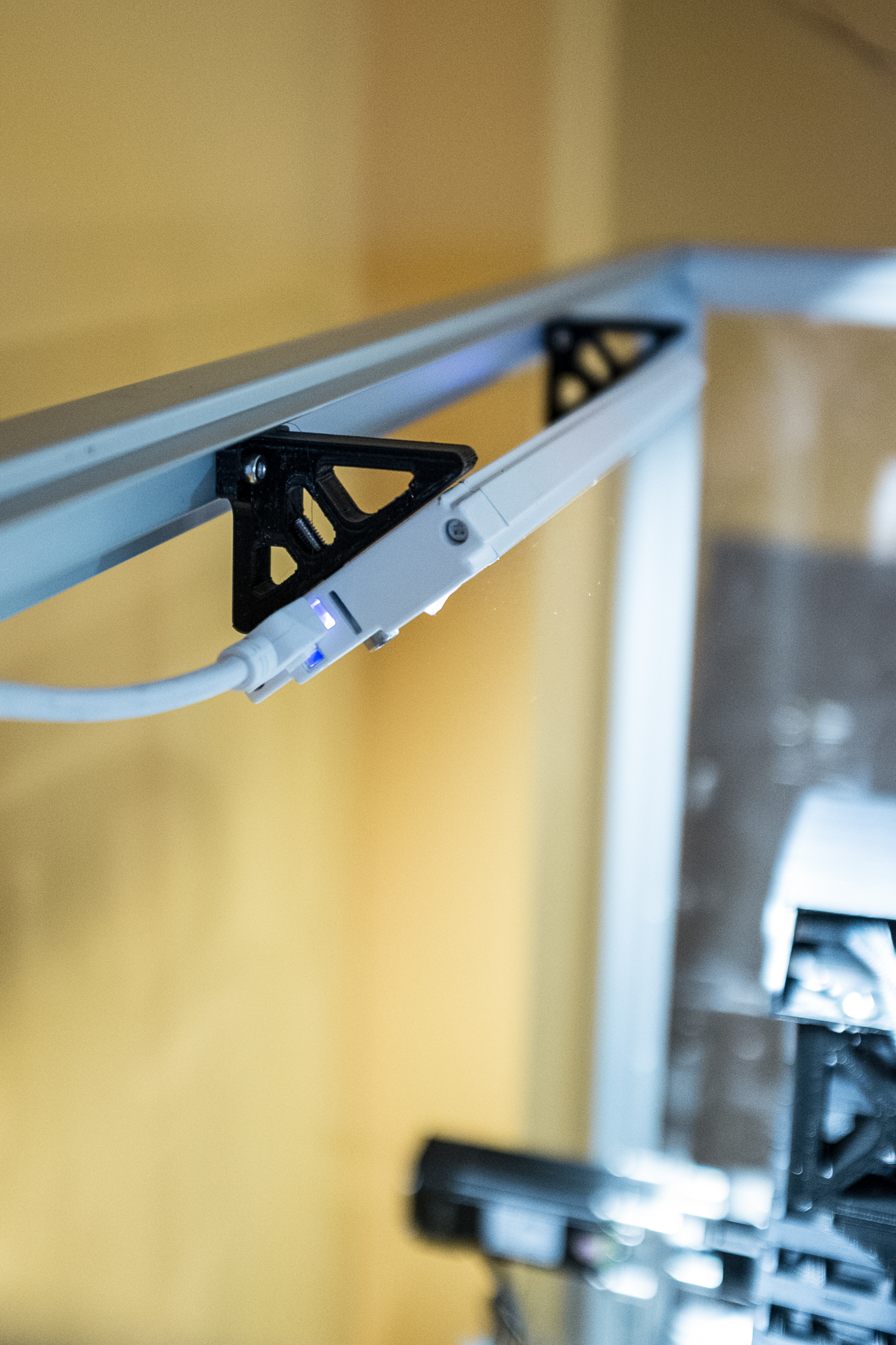
Finally added the top drag chain and it got mounted to the 3d printed brackets. I know the two pieces don’t align and I should print another one to make it look a tad better but it was super late at night when I was designing it, plus for now it does the job perfectly.


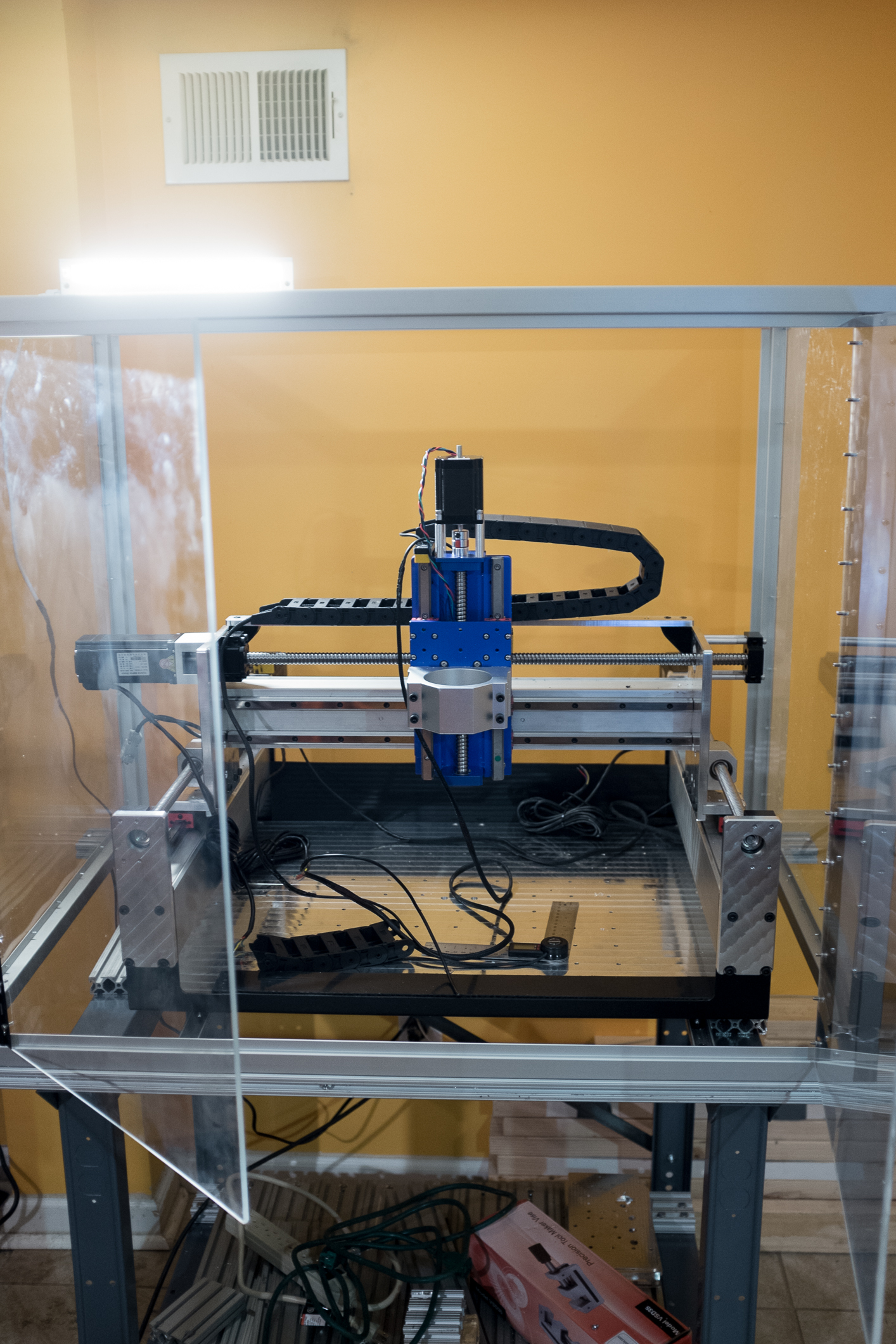
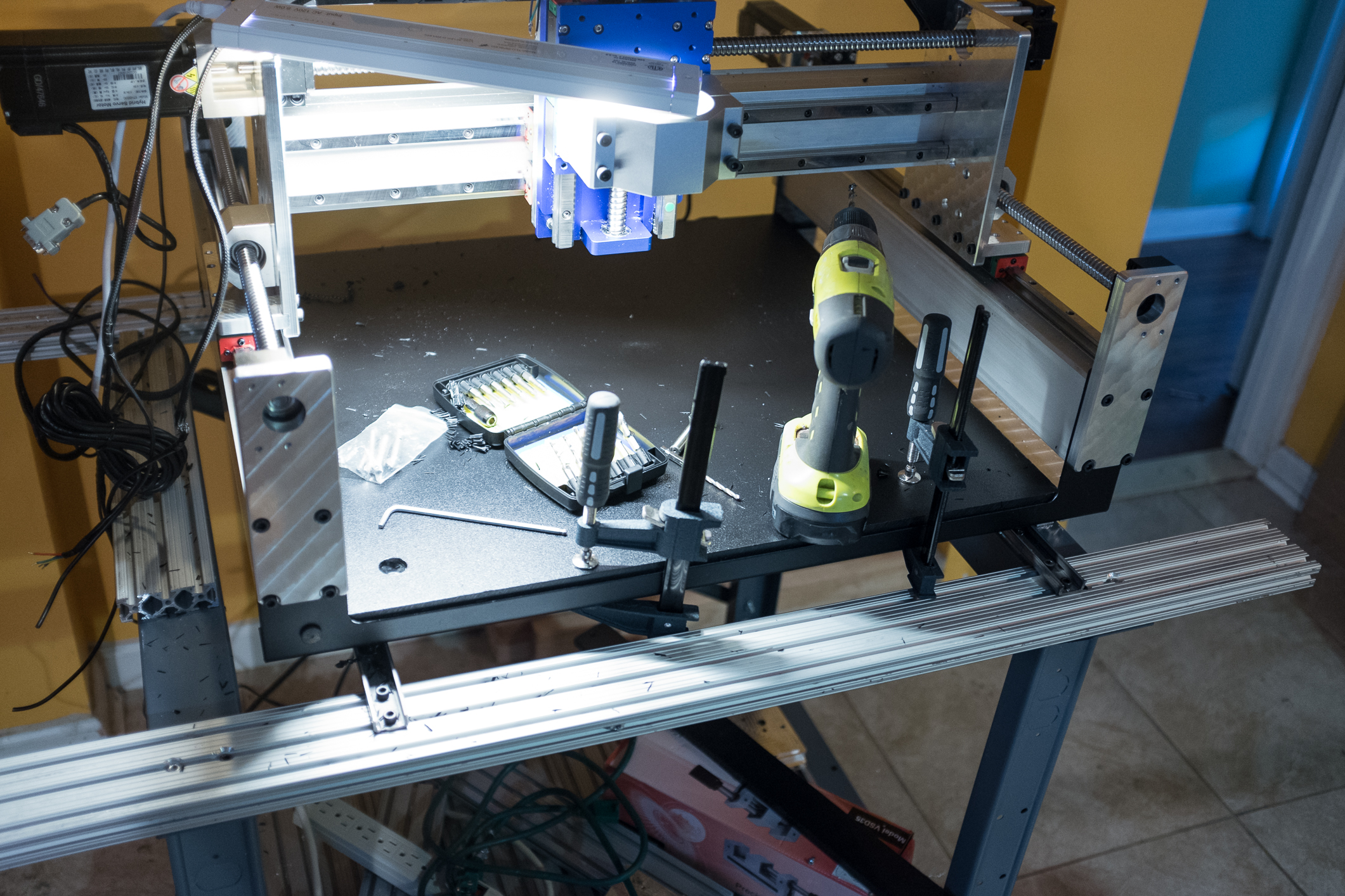
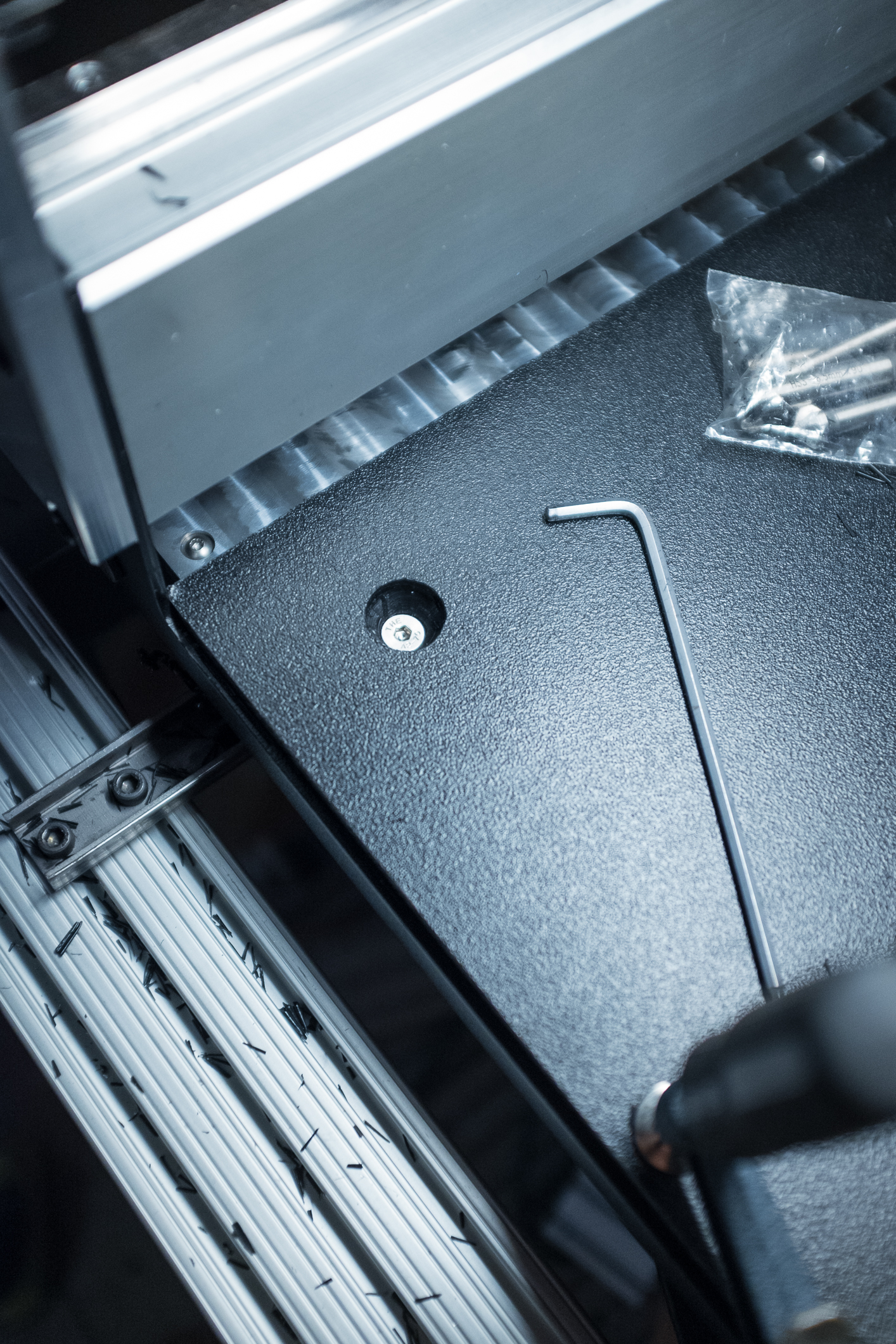
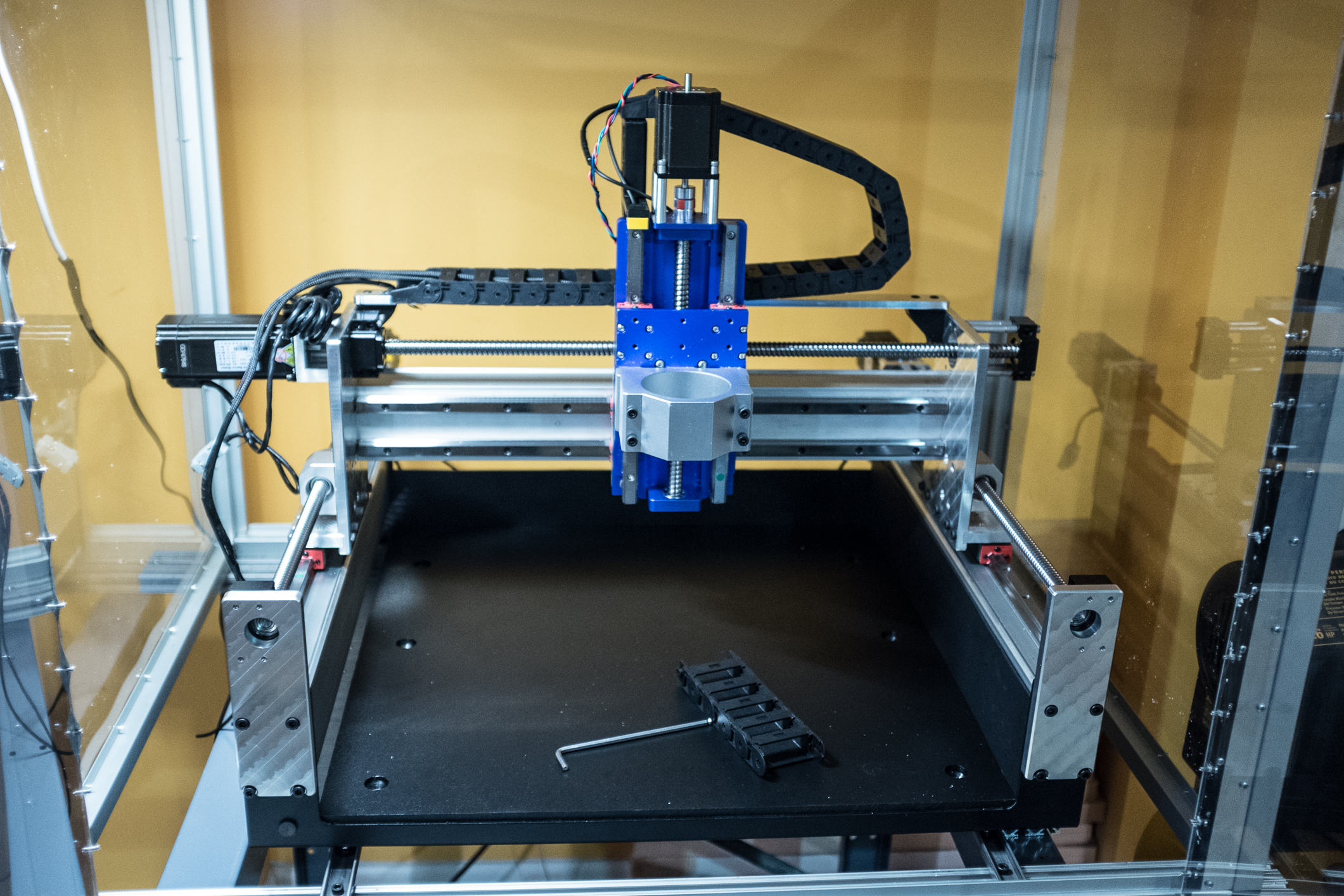
I’ve been waiting for about a week for the 3/4" hdpe board to arrive but it’s finally here. 24x24 board had to be shorten about 1/2" to fit on the so3’s bed but it was easily done with a jigsaw. Clamped it to the table, drilled small pilot holes from the bottom through the aluminum table’s threaded holes and then re-drilled them from the top. Used m6 countersunk bolts to mount the board to the table and made sure that the holes are plenty deep. Board will have to be surfaced and tapped before the actual aluminum table will be installed. Still need to add bolts in the middle part of the table but that won’t happen before I know what is the exact size of my cutting area. Don’t want to crash into a steel bolt while drilling the holes. Enough talking here are the pics.

Maybe silly thing to mention but I’ve also designed some small brackets for the led under cabinet lights that I had laying around. Will have to add another one on the side of the enclosure.

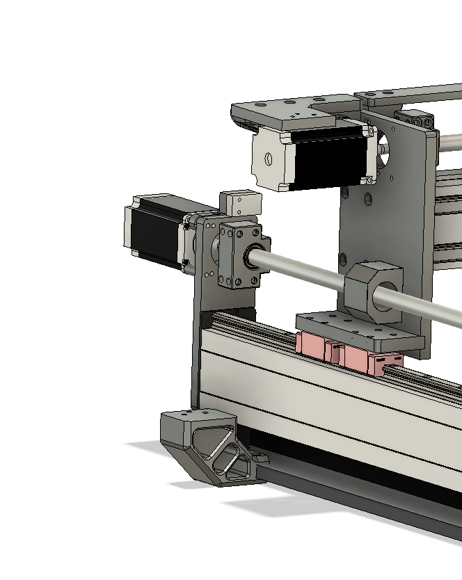
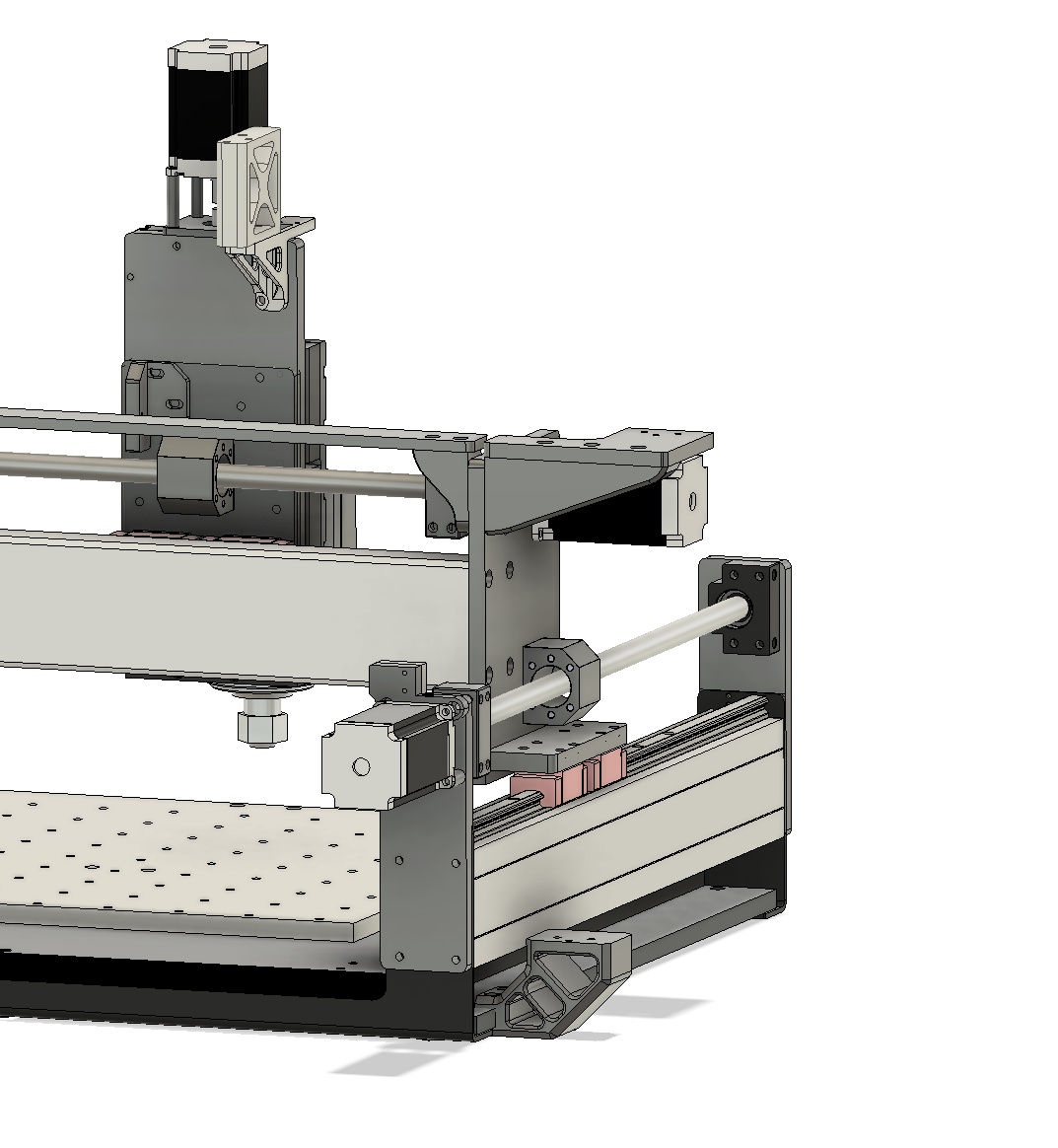
Started working on the second drag chain but all I managed to do was mach up the placement of the top part that will be installed near the x axis motor.


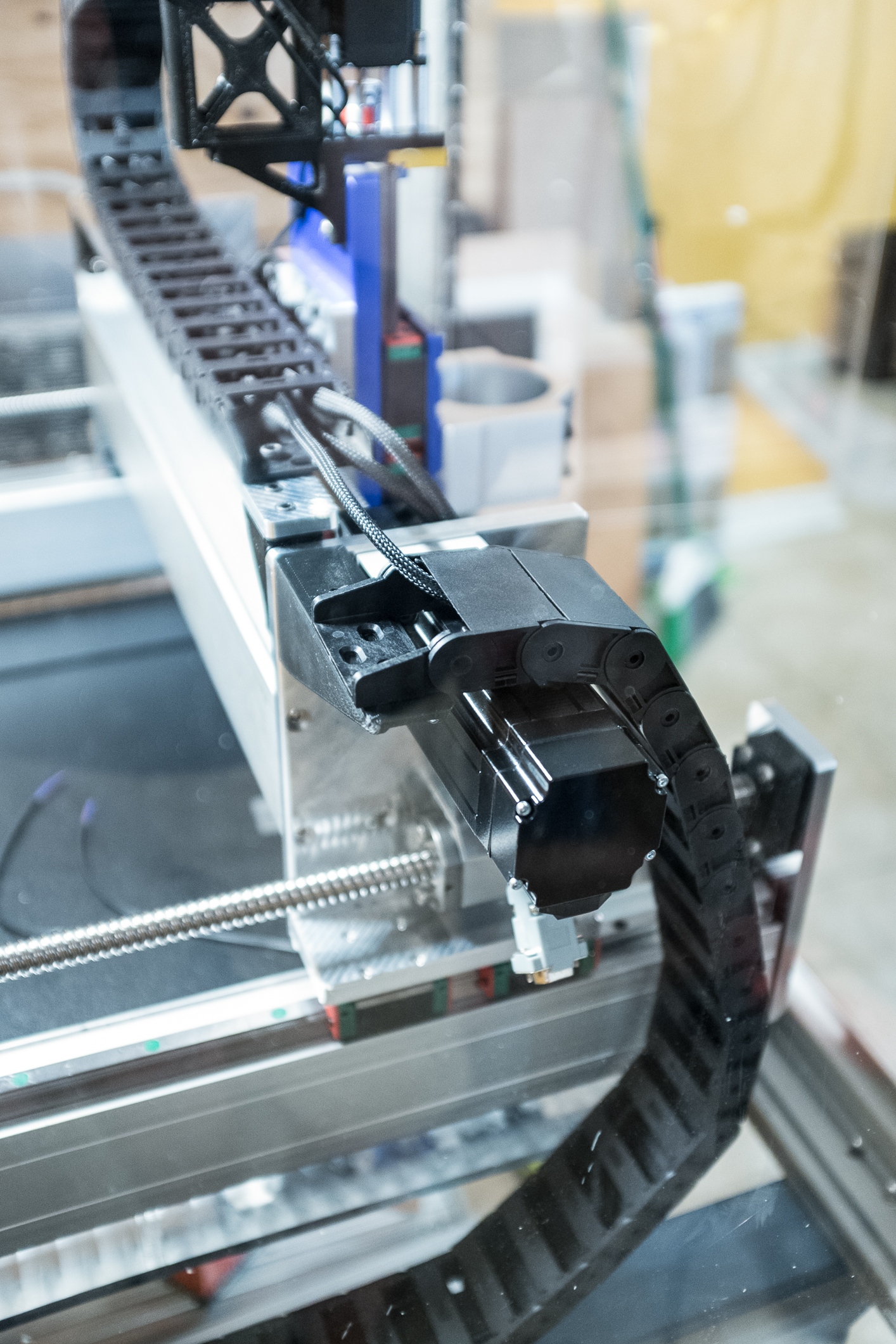
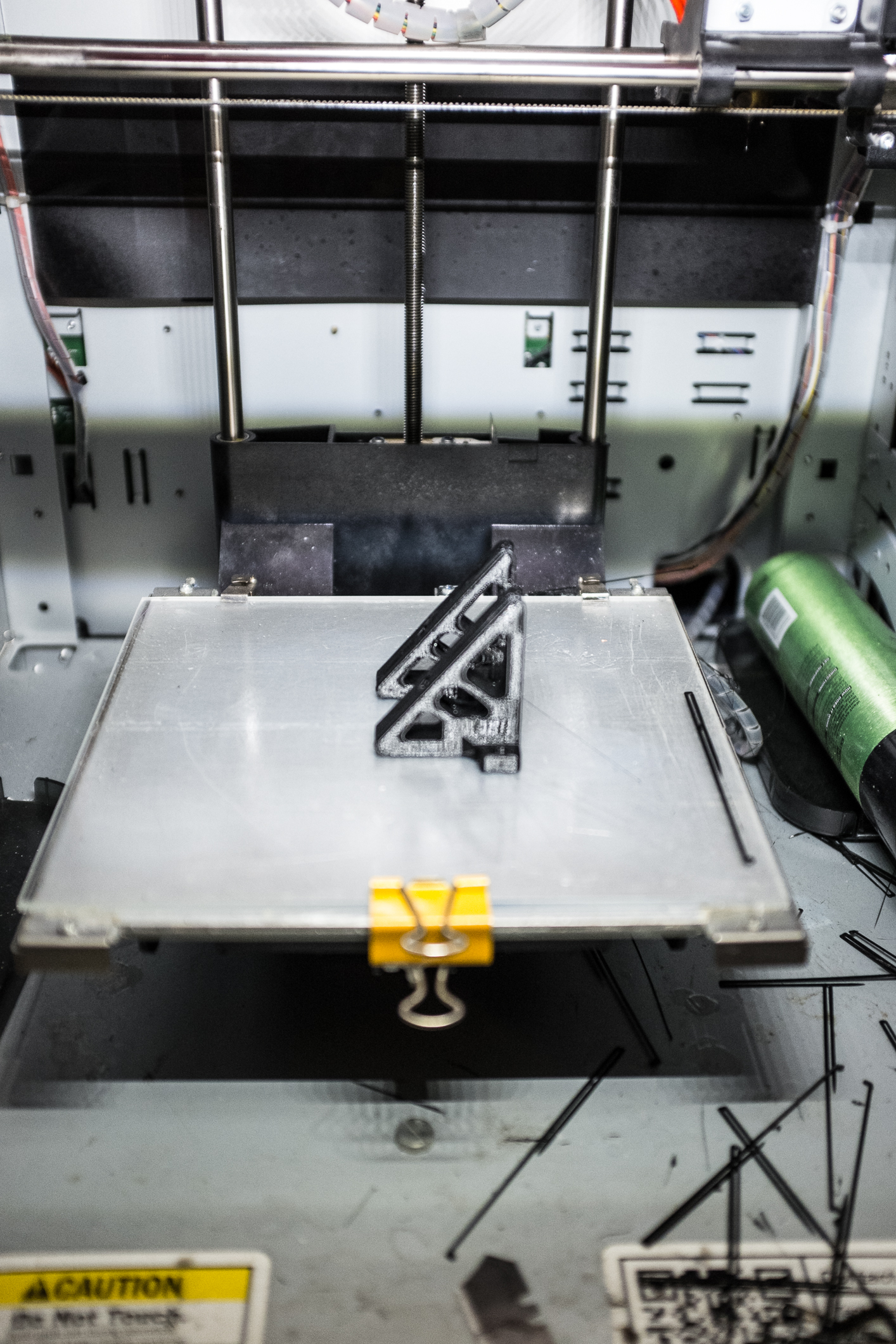
I know it doesn’t look that well yet, because I still need to cut a aluminum ‘shelf’ that the chain will be bolted to. It should extend over the motor. Didn’t want to go with fully 3d printed one because don’t know how hot those motors will be getting while energized. They’re closed loop so in the theory should be significantly cooler than regular steppers but better safe than sorry. Don’t wan’t to have a melted PLA stuck to the motor. When done it should look like this ->

The bottom chain bracket will be bolted to the original aluminum table.

Hopefully my power supply will arrive this or the following week, so before that happens need to have a electronics enclosure designed and made. I’m thinking of mounting everything to the 1/4 aluminum plate and have corners 3d printed. I’ll show exactly what I mean some time this week. I could go with a pc case like I did on my other machine but this solution should be easier and look better.

Thanks for reading :+1:

6 Likes

Only a small update today. The machine is coming together great. Finally received 10mm to 8mm ballscrew couplers. If anyone ever need them here’s a link to the ones I used. https://www.aliexpress.com/item/32934175994.html?spm=a2g0s.9042311.0.0.17184c4db7Ku5u

The quality is great, price was amazing (for 4pcs paid less than it would cost to source a single one from eBay or Amazon) - paid $12 for 4pcs, they arrived in 2 weeks and had no problems fitting them on to the machine. Maybe nothing to be particularly excited about but ordered some couplers from Amazon in the past ($20/piece) and had to re-drill them because they wouldn’t fit.

Anyways, couple of things I managed to finish recently.

Drag chain bracket printed and installed. It looks way better in person than in the picture. Shame it’s not visible at all. lol

Installed the top drag chain bracket. Extended stepper motor and limit switches’ wires and put them in a braided sleeve to clean up the look a little bit.

Closed loop water cooling system is scheduled to arrive today, and the spindle is supposed to arrive tomorrow so I’m basically only waiting for the 60v psu to be able to test this bad boy. I’m in a middle of working on the electronics enclosure. Milled a plate yesterday and laid out some of the components to make sure everything fits.

In another thread I complained about having bad experience with Chinese aviation connectors for the stepper motors so I’m only going to use them for the limit switches and other low voltage accessories while the stepper motors will be secured to the enclosure with cable glands. I’m using closed loop 428oz steppers on X and Y axis and 270oz open loop stepper motor on the Z axis. Z motor will be connected to the driver on the xpro board and powered with 24v psu while X/Y motors with 60v psu. This should easily allow to achieve rapids of 3000mm/min on the Z axis and I think that’s plenty, but if I ever need it to go faster I’ll just add another external stepper driver to the mix.

Don’t know why Fusion360 didn’t update the file I was working on on the other computer so here’s a screenshot of how the work on the electronics box started just to give you a rough idea of what I’m trying to achieve here. 3d printed corners with maybe acrylic side walls. Something along those lines.

8 Likes

There has been quite significant progress in the last couple of days. New 110v 1.5kw water cooled spindle with er16 collet arrived. They’re surprisingly not that easy to find as most of 1.5kw ones have er11 collet.

Here’s a link to the one that I purchased https://www.aliexpress.com/item/33060583401.html?spm=a2g0s.9042311.0.0.1a514c4d867UI3

Seems well built and looks much nicer than my 2.2kw spindle but I’m sure there isn’t much difference in the build quality. Of course it didn’t come grounded (even though seller specifically said it is) so had to add a wire to the pin #4 and bolt it on the inside of the cap.

I’m still waiting for the spindle cable to arrive but should be here around Wednesday this week. This is the one I bought. https://www.ebay.com/itm/CNC-VFD-Cable-10ft-16-4-Double-Shielded-For-Spindle-8Kw-1-5Kw-2-2Kw-4Kw-4-5Kw/142538105021?hash=item212feee0bd:g:QlkAAOSwFFZbJ8Gz Ordered it so late because, until the last moment couldn’t decide if I really want to spend $40 on a piece of cable. I’m using this exact cable on my other cnc and I know it’s a way to go, but it seems like a lot of money. Was considering just getting 16/4 wire and see what’s gonna happen but it’s only $15 cheaper for the same length. I know other users reported no problems running unshielded cable in much thinner gauge but I just want to do this thing right and be done with it.

Closed loop water cooling arrived as well. Yuppy yeeeyyy, only problem was that the water pump’s casing had a crack around the thread. Seller already sent a replacement one but since they didn’t have just the pump in the US warehouse, they had to ship it from China. Tried fixing the crack by plastic welding it so we’ll see how long will it hold.

Made a bracket to attach radiator and a water pump to it.

And the view from the inside of the enclosure. Slots were cut into the plate mostly to allow for the airflow (not sure if that’s necessary or not though) but also to look good from the other side.

Added this cute little water flow meter/indicator. Just waiting for a 3/8" to 1/4" reducers to fix it permanently. For now taped the ends of a smaller diameter tube with an electrical tape and slid them into a larger tube but it’s a very shabby solution and will most likely start leaking immediately after putting coolant into the system.

Machine’s enclosure is nearly finished, so the last thing to do is to connect all the electrical components and start testing the machine. Figured it would be best to install electronics box in the back.

Still have to figure out the exact layout of electronics.

And finally, this is how the whole machine looks right now.

7 Likes

I will be interested in getting feedback on then 1.5kW spindle since you had the 2.2kW before. Going to 1.5kW is easier for most users as you can install a 20A 120v circuit easier than a 240v, the spindle is smaller and maybe the power difference will not affect the projects you are considering.

2 Likes

Nice and clean setup, an inspiration to all.

Your control board is a Spark Concepts xPro V4 I believe? I have the same and have been unable to initiate PWM control although it seems it should be quite simple. Please let me know the steps you use.

@luc.onthego I’m pretty sure there won’t be much difference. My 2.2kw spindle is also 110v and at the time of buying it I didn’t know much about spindles, single phase or 3 phase power etc. Spent a lot of time reading about them on cnczone and according to people much smarter than me (and I believe they’re right) 2.2kw spindle on 110v only puts out about half of the rated power so there really shouldn’t be much difference. I won’t go into much detail, especially that I can’t properly explain it, but I’ll gladly share my subjective opinion once I’ll do some cuts with this machine.

@Griff thank you. Yes, Im using xpro v4 on my other cnc router as well and really had no problems with it. If you followed the instructions in the spindle thread (and I’m sure you did) and after setting all the parameters correctly removed the jumper to allow external controls it should work. It’s literally as easy as connecting two wires from the xPro to the vfd. One issue however that I have is that my rpms are off by about 200rpm no matter what. :confused: that’s something I couldn’t figure out myself and even flashing grbl didn’t help. Once everything will be hooked up I’ll take pictures for those who’d be interested to see how everything should be connected.

1 Like

Ah ha, he says. Missed the jumper reference. Is that on the xPro or the VFD?

1 Like

VFD, little red guy on the right hand side of the terminals. Very easy to miss it.

Edit - sorry actually it’s not red. :wink:

400px-VFD_wiring_diagram

1 Like

I can see running the 2.2kW on a 15W circuit would give you between 1.5 an 1.6kW max, on a 20A circuit should be able to give you close to the 2.2kW. If you can, run a 20A circuit to your workstation, it would give you better performance at or near max spindle power as you would exceed 80% of your 15A circuit at max power.

2 Likes

Well…a jumper, how’d I miss that? Been checking, re-checking, soldering, re-soldering for a few weeks now.

Somehow I never saw a reference to a friggin’ jumper.

So simple (as I knew it would be).

Thank you sir.

1 Like

@luc.onthego I’m gonna have to look into that. I’ll definitely check whether I’m running on a 15 or 20amp breaker. One thing that will make a comparison a tad difficult is that my bigger cnc’s gantry has more deflection than shapeoko does. It would be perfect to test 2.2 and 1.5kw spindles on the same machine. As much as I would love to do that I’m dreading the idea of going through tramming both machines to perfection again and again and again haha

@Griff glad it worked.

1 Like

Normally, the 20A receptacle would look like this image

If you decide to go with this, don’t forget that you should also have higher guage wire. Around here 15A runs on 14Ga while 20A uses 12Ga… and the different plug like the one above to identify the 20A circuit.

1 Like

Awesome, thank you. I’ll check it out tomorrow. But now that I’m looking at this pic I’m almost sure it’s 15A.

Don’t know if this has been solved yet but I find comm issues with Serial or USB devices are often caused by poor quality USB cables. I use a 20-foot high-quality USB with gold plated connectors and have no issues. The 20 length I use is way past recommended but works well with a quality desktop machine. There are many causes of noise in a system but with serial devices, noise is always a problem I am amazed at the robust nature of USB compared to old serial. In the old days as in 300 Baud, any noise would crash a system. Also If your booting up each time you use the system there may be a USB conflict with other devices when the system assigns interrupts. Hope this helps

As I struggle to get my drag chains installed properly on mine, I love how you did yours. I will mill out some new platens for them to rest on and install a side one as well.

Your cable management is great too. What are those black mesh sleeves you use that your cables go into?